| |
Orifice Flow Control System for Very Long Gas Supply Hose
Cuts Waste -Typically Saving Half the Shielding Gas Used!
Can also be used with cylinder gas supply*
Gas Saver System with Flow Control Orifice:
Some fabricators, with very long gas delivery hoses (over 100 feet) from their gas supply want to use our Gas Saver System (GSS .) They also can accept setting shielding gas flow at a fixed rate using orifice flow control. We have a shielding gas saving patent (see footnote below) that defines a product achieving the gas saving and improved start features of our GSS. This product connects to the end of a very long gas supply hose while providing a fixed flow rate. It is called an OGSS-45 for Orifice controlled Gas Saver System and satisfies this need with no moving parts. It is designed to operate with a fixed flow for a typical 50 psi pipeline and can also operate with other pipeline pressures.
IMPORTANT: Note for up to a ~75 foot long gas delivery hose it is typically less expensive and more effective to put an orifice (or any quaity flow control) at a pipeline drop and use a standard GSS to set flow and save shielding gas. For cylinder gas supply, if it is desired to lock flow setting adjustment, a standard GSS can be used and a Regulator/Flowmeter incorporating our patented FRL (Flow Rate Limiter.)
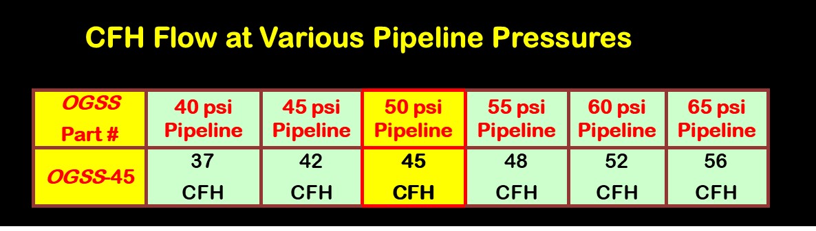
 1) The inlet side of the OGSS-45 uses a fixed orifice that controls flow on a typical 50 psi pipeline at 45 CFH. If the pipeline pressure varies from 50 psi the flow will change per the table below. (Note the OGSS-45 can be used with cylinder gas supply by using a standard pressure regulator with the output set set to 50 psi. If a TIG RIG is used on a truck with very long lines, a standard pressure regultor can be set at about 25 psi providing about 25 CFH TIG torch gas flow.) 1) The inlet side of the OGSS-45 uses a fixed orifice that controls flow on a typical 50 psi pipeline at 45 CFH. If the pipeline pressure varies from 50 psi the flow will change per the table below. (Note the OGSS-45 can be used with cylinder gas supply by using a standard pressure regulator with the output set set to 50 psi. If a TIG RIG is used on a truck with very long lines, a standard pressure regultor can be set at about 25 psi providing about 25 CFH TIG torch gas flow.)
2) The GSS custom extruded hose section performs a reservoir storage function retaining a controlled amount of extra gas every time welding stops to provide superior subsequent weld starts.
3) The OGSS-45 male outlet “B” fitting simply screw it in to a welder or wire feeder. It contains a peak flow limiting orifice that controls the maximum start gas purge flow rate to prevent excess turbulence in the shielding gas stream. It prevents the typical weld start “gas blast” that pulls air into the gas shield causing inferior weld start quality.
|
The Patented WAT OGSS-45 is Easy to Install and Use.
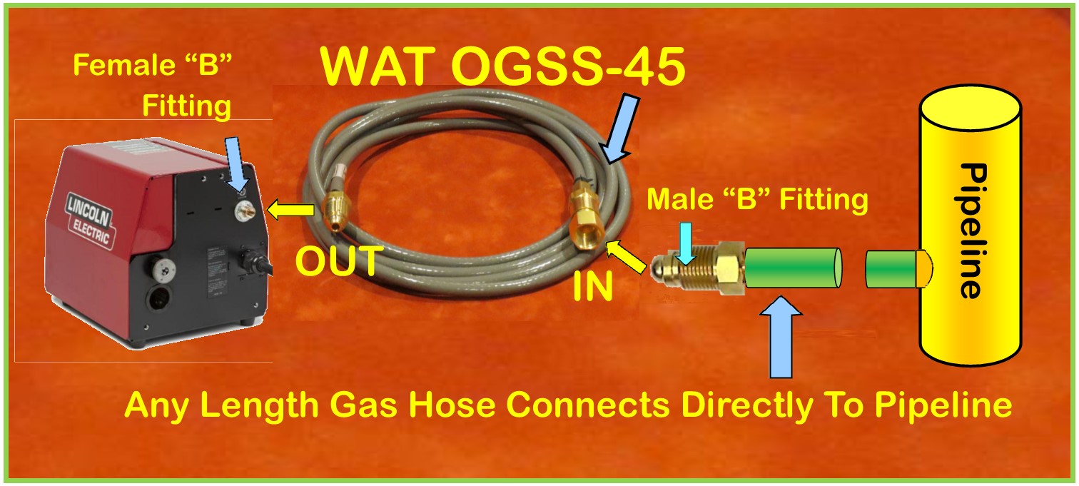
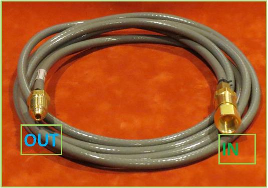
The OGSS-45 simply attaches to an existing gas delivery hose of any length or ID that is connected directly to a pipeline (or cylinder pressure regulator) with NO flow control needed. It sets the gas flow rate based on the pipeline (or regulator) pressure. The INPUT END has a female “B” fitting to except a male “B” hose end (Noyt we can also supply a 1/4 inch hose barb to be spliced into a 1/4 inch ID hose.) . The OUTPUT END has a male “B” fitting that SCREWS INTO the typical female “B” bulkhead fitting on most welders, wire feeders or welding robots.
SETTING PRESSURE
The pipeline pressure can be adjusted per the table below to achieve the exact flow rate desired. That can be done for pipeline supply at the liquid gas supply evaporator, at a gas mixer or employing a high flow capacity regulator installed in the pipeline system. (Note, if cylinder gas supply is being used set the outlet pressure with a conventional pressure control regulator.)
BENEFITS
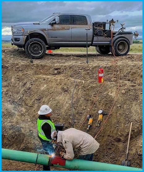
The WAT OGSS-45 connects to the outlet of very long length existing hoses as used in some shipyards. It not only reduces gas waste but it also provides a fixed flow that won’t change with the inevitable variations in flow restrictions encountered while welding. If a Truck mounted Welding Rig uses very long welding cable and gas delivery hose for TIG welding it can be useful employing a conventional 50 psi adjustable output regulator on the gas cylinder. Note that is a conventional regulator NOT one that sets CFH. |
Why Don’t Welders Like Orifices, Flow Control Regulators or Flowmeters Mounted at the Wire Feeder?
Welders see the result of lack of initial purge gas as inferior starts with excess spatter. They may not understand the cause of the inferior arc starts but they can observe the result! Many have experienced similar poor starts while welding with cylinders and forgetting to turn on the gas valve (as have I! ) When starting without a quality gas purge, the weld starts have high spatter and possible internal if not visible porosity.
If welders have the ability to adjust flow rates, such as when using a needle valve controlled flowmeter or a regulator with a flow adjustment mounted at the feeder, they will increase the steady state flow in attempt to improve weld starts. Increased steady state flow can help but cannot quickly provide a controlled amount of needed extra purge gas as the OGSS delivers. It also wastes gas defeating the original “gas saving” objective!
Footnote: US Patent # 7,019,248
Bottom Line:
If you think your application can benefit from our patented OGSS, Email TechSupport@NetWelding.com with your 1) pipeline pressure, 2) length of gas delivery hose from pipeline to wire feeder 3) number of welders and 4) desired flow rates.
*Note:
can also be used with cylinder gas supply by using a standard regulator, setting output to 50 psi. Useful for truck mounted engine driven welders that often use 100+ foot long lines for TIG or MIG.


