
Sales Literature
PDF
Download
WA Technology
 Save MIG
Shielding Gas and Improve Weld Start Quality. Save MIG
Shielding Gas and Improve Weld Start Quality.
Cut Gas Use in Half by Eliminating Waste!
OVERVIEW:
FOLLOWED BY DETAILS
THE PROBLEM:
 |
MIG welders use from 3 to 5 times the
amount of shielding gas needed; costing over $1000
per year per production welder.
|
WHY GAS
WASTE OCCURS:
|
At each weld stop, gas flow continues
through the needle valve or orifice flow control and fills the gas
delivery hose with significant excess gas. |
|
At every weld
start, the extra stored gas “blasts” out of the MIG gun nozzle at a
very high flow rate not only wasting gas but the turbulence created pulls in air causing inferior weld quality. |
SIMPLE, LOW
COST, PATENTED SOLUTION
|
Our Gas Saver System (GSS )
reduces the gas surge at weld starts by 80 to 85% primarily by using a custom extruded, small ID, heavy wall thickness, reduced volume hose.
|
|
The
GSS reduces the peak surge flow rate using an orifice; avoiding turbulence and moisture laden air
it pulls into the gas stream. This also adds to reduced gas surge volume waste.
|
|
The GSS typically accomplishes a 40 to 50% "total gas use reduction" with no moving parts,
pressures to set, or knobs to adjust.
|
|
Simply
replace the existing gas delivery hose with the
GSS. |
|
Over 15,000 GSS's in Use! Welders LOVE the improved weld starts! |
|
|
DETAILS: SCROLL DOWN
THE PROBLEM:
The typical user of MIG welding consumes from 3 to 5 times the amount of
shielding gas needed. Two published reports quantify these estimates.
 An
article in the Fabricator magazine entitled “Shielding Gas
Consumption Efficiency,” states the average fabricator uses from 18 to 30
cubic feet of shielding gas per pound of wire consumed. This is 2.5 to
5 times
the amount that is needed or up to 80% wasted gas! They also define that
the gas flow surge at the weld start is a significant cause of the waste. An
article in the Fabricator magazine entitled “Shielding Gas
Consumption Efficiency,” states the average fabricator uses from 18 to 30
cubic feet of shielding gas per pound of wire consumed. This is 2.5 to
5 times
the amount that is needed or up to 80% wasted gas! They also define that
the gas flow surge at the weld start is a significant cause of the waste.
An article in Trailer Body Builders magazine
quotes a representative from a leading
producer of shielding gases, Praxair, indicating their
production site surveys show the
average fabricator consumes 30 cubic feet of gas per pound of MIG welding wire
when only 5 cubic feet per pound may be needed! They state, this is up to
6 times what is theoretically needed!
Depending on the price paid for shielding gas, the gas delivery pressure, the
amount of arc time, the gas delivery hose length, and the frequency of MIG gun
trigger pulls, this gas waste can cost well over
$1000 per year per welder.
|
|
SIDE
BAR
Why Has My Shielding Gas
Supplier Not Told Me How to Fix the Gas Waste Problem?
Understanding and quantifying issues and reasons of shielding gas waste is rather
complicated. I managed a 35 person Welding Material Technology R&D Laboratory for a
leading producer of shielding gases and filler metals (was called Linde then changed their name to Praxair when they divested of the welding equipmet, cutting machines & filler metals busnesses. Now bought by the original Linde AG from Germany-expect it will be back to Linde for all! LOL) At the time, they
produced about half of the Argon in the USA. We had a big influence on Argon price. Today Three foreign companies have 84% of the US Argon prodcution, Air Liquide (French) who recently bought Airgas, Linde AG (German) and Martheson (Japan Oxygen.) We
developed MIG and TIG shielding gas mixtures as part of our development
effort. Neither myself or our group of engineers, metallurgists and
skilled welding technicians could have
defined the main reasons shielding gas waste existed! We knew it did, since when Argon
was in short supply, as it often was at that time, the company would help
large customers with hundred's of MIG welders such as shipyards and offshore drill
rig production, reduce waste by suggesting maximum flow rates, finding and fixing leaks, etc! We were
aware a minimum of 25 psi gas pressure above the flow control orifice or
needle valve was
needed to achieve "automatic flow compensation." That keeps preset gas flow constant with the
inevitable flow restrictions that occur in the MIG gun cables, spatter in the gas
diffuser and nozzle etc. We also knew the high gas pressure created an
excessive gas surge at the weld start that had a negative effect on weld
starts and gas waste. However we did not conduct the research to
quantify the main reasons for gas waste and often would subjectively blame leaks
since that was out of our control!
Of interest, the results of
fabricator surveys were recently mentioned in a published article by a
representative from that same industrial gas manufacturer (Linde/Praxair) stating the average
fabricator uses up to five times the amount of gas they should!. Note, Argon prices have more than tripled in the past few years. Praxair, a leading Argon producer, raised prices 35% in 2016 and 15+% increase January 2017. Air Products followed with a price increase of 20% and Airgas 15+% in the 1st quarter of 2017. Air Products anounced a 20% increase in 2018 , another 20% in January 2019, 20% February 2020 with another 15% in October 2020! Argon is less than 0.9 % of the air and is in very short supply. The ~4 gas liquefaction companies in North America will continue to keep demand matching supply (and increasing their profits) using price as they always have! CAN'T ECONOMICALLY IMPORT ARGON FROM CHINA! In fact we have shiped over 800 of our pateted Gas Saver Sytems to fabricaros in China! The last 250 systems shipped September 2019!
I recall a Lincoln Electric brochure years ago about Innershield flux cored wire
(which
doesn't use shielding gas) that stated in a section on costs; "We all know
how much shielding gas is wasted." They were refereeing to the
standard MIG gas cost calculations, which uses flow rate multiplied by arc-on
hours to define gas use - which we knew was bogus! But how were we to put in a
typical gas waste in the calculations when we could not predict the
amount? And frankly, the company and all sales folks were selling
shielding gas! Of interest I see this same bogus cost calculation approach being used in technical reports today. (See
Gas Cost as Percentage of Welding Cost Information.)
Since forming WA Technology 20 years ago, we have made thousands of weld
start and gas waste tests in our lab and hundreds at users. After
our extensive testing and customer visits we have found the gas surge at the
weld start is often the most significant cause of shielding gas waste - NOT
LEAKS! We have
evaluated a number of devices to reduce waste before inventing and patenting our
simple, low cost Gas Saver System (GSS).
A number of our customers have quantified the gas savings achieved by properly
controlling gas surge at the weld start (typically, total gas use can be cut in
about
half.)
We have tested and understand why other approaches some have tried to reduce gas waste frustrated welders and have been altered, misused or removed
such as Gas Guard and other low pressure devices, simple orifices, moving the flowmeter to the
wire feeder etc. We have also observed that welders appreciate our
GSS reducing peak flow at the weld
start while it still provides a controlled amount of extra gas to purge air
in the weld start area without excess flow rate causing turbulence. In addition, our
GSS does not interfere with
the welders
ability to set reasonable flow
rates with a standard flow control device. However if they are setting very high flow rates the GSS will limit the maximum flow to about half the 150 CFH that can be set on a flowmeter with the knob opened excessively. If limiting maximum allowable flow settings to stay within Welding Procedure Specifications (WPS) is desired, we have another
patented device that locks the flow control knob on most flowmeters. See
Flow Rate Limiter.
Another, and major reason why your gas supplier may not have taken the time to
fully understand why gas waste occurs and why past solutions tried
don't work,
is their FINANCIAL DIISINCENTIVE TO DO SO!!! In many cases gas sales and cylinder rent are 85+% of their profits and therefore their sales focus! Our simple, low cost GSS is patented; it is unique. It
not only lowers the peak flow starting surge rate, it reduces stored gas when welding
stops by ~85%. This is due to the reduced internal volume, less hose expansion and the peak flow control orifice. That still leaves enough extra gas at high pressure to quickly purge air from the weld start area.
It will usually pay for itself in a very short time and saves gas and costs
for many years.
 Well over 15,000 thousand GSS's are in use - it works! Well over 15,000 thousand GSS's are in use - it works!
Our patented GSS is sold here on our website and "NOT in Welding Gas Supply STORES." If you want a full explanation of
gas waste and the solution, read the Technical Paper prepared from presentations
given on the subject in numerous talks in the US and abroad - CLICK
for FREE PDF
CLICK TO SEE GSS PURCHASE PAGE, PRICES START AT $70.00 |
|
MEASURING YOUR GAS WASTE
Measuring your shielding gas waste is straight forward.
For example, if 0.035 solid MIG wire
is being used, welding at 200 amps, the deposit rate is 6 lb/hr of wire for every hour of arc time. A shielding gas flow rate of 30 CFH
would be more than adequate. Therefore for every pound of wire consumed 30 CFH / 6 lb/hr or
5 CF of shielding gas. Check past purchases
of MIG welding wire and shielding gas for the same time period and compare.
Don’t be surprised if they are over 3 times what they theoretically should be!
The table below shows
the typical gas to wire ratio needed for various wire sizes. A typical
deposition rate for 0.045 solid or cored, is about 8 lbs/hr. Using
35 CFH gas flow rate, that should consume 35 CFH/ 8 lbs/hr or 4.4 CF per pound
of wire used or 15.7% of the 30CF/lb reported in the published article by a
gas supplier representative! We have found similar large excesses in our
decisions with fabricators!
|
|
The accompanying table provides some deposition rates for typical wire types,
sizes and amperages. Check out the far right column and note published survey
data states the average MIG welders uses 30 CF of Gas Per /lb of wire used! |
|
Wire Type |
Size |
Amps |
Lbs/hr |
CF Gas/ lb Wire Used |
|
Solid |
.035 |
175 |
5.5 |
5.5 CF |
|
Solid |
.045 |
225 |
6.8 |
4.1 CF |
|
Cored |
.045 |
250 |
8.5 |
3.5 CF |
|
Cored |
1/16 |
300 |
10.2 |
2.9 CF |
|
Another way to
provide an estimate of shielding GAS Waste can be made using the data in
the far right column. Select the wire type and size from the chart
above and the average amperage used. Not sure about the amperage -
use the highest shown in the table to be conservative. These data is
based on using 35 CFH flow rate.
Example: You used 46,000 lbs of 0.045 solid wire and your average
amperage is about 225 amps. Than multiple 4.1 CF Gas/1 lb wire X
46,000 lb = 188,000 CF of gas you should have used. But you purchased
590,000 CF of gas. Therefore 590,000 - 188,0000 = 402,000 CF was
wasted or 402,000 Wasted / 590,000 Purchased =68% wasted! |
|
FOOTNOTES: Purchasing
CO2
in pounds? 1 pound of
CO2
= 8.7 CF gas at STP
Purchasing liquid Argon in
gallons? 1 gallon of liquid Argon = 113 CF gas At STP
NOTE: I was amused when a customer told be they were buying Argon in gallons! In my former business life I trained bulk gas salesman on the technical welding areas (not easy as they had little interest!) I also attended some of their sales training - a unique experience. They are well trained to obtain and retain business using long term contracts. It's purposely difficult to define the volume and price per cubic foot of the bulk liquid gas your buying! Be assured they know the exact amount but when asked are always concerned you might be looking for a lower priced vendor! May have to pry the info from them and assure them you're looking at welding efficiency NOT to replace then as a supplier!
Want More Details of Calculating Gas Waste?
|
|
A MAJOR CAUSE OF GAS WASTE
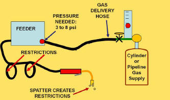 The
figure left, schematically shows a typical MIG welding system.
While welding the regulator/ flowmeter drops the pressure from the cylinder or gas pipeline
to that needed to deliver the required amount of shielding gas to the MIG gun. The
figure left, schematically shows a typical MIG welding system.
While welding the regulator/ flowmeter drops the pressure from the cylinder or gas pipeline
to that needed to deliver the required amount of shielding gas to the MIG gun.
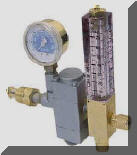
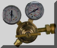
Regulator/Flowmeters (Photo Below Left) outlet pressures range from 25 to 80
psi. For CO2 shielding 80 psi is used
to help prevent ice formation.
Flowmeters
on pipelines allow pipeline pressure to exit the flow control valve when
welding stops. A typical pipeline pressures 50 psi.
Regulator/Flowgauges (Photo Below Right) operate by setting a pressure
above a very small critical orifice (typically about 0.025 inches.) For most MIG shielding gas flow rates the
pressure when welding stops will range from 40 to 70 psi.
 However,
the pressure needed at the feeder to flow the
shielding gas though the solenoid, fittings and MIG gun can range from 3 to 8 psi depending
on MIG gun cable length and restrictions. Every time welding stops, gas continues to flow through the needle valve or
critical orifice and increases the pressure and gas volume in the delivery hose to that of the
regulator output or
pipeline.
Therefore, the pressure in the gas delivery hose will
be about 25/3 = 8 to 80/3 = 26
times the pressure needed to flow the desired amount of gas! For
Flowgauge/Regulators the pressure is 13 to 23
times what may be needed! However,
the pressure needed at the feeder to flow the
shielding gas though the solenoid, fittings and MIG gun can range from 3 to 8 psi depending
on MIG gun cable length and restrictions. Every time welding stops, gas continues to flow through the needle valve or
critical orifice and increases the pressure and gas volume in the delivery hose to that of the
regulator output or
pipeline.
Therefore, the pressure in the gas delivery hose will
be about 25/3 = 8 to 80/3 = 26
times the pressure needed to flow the desired amount of gas! For
Flowgauge/Regulators the pressure is 13 to 23
times what may be needed!
 When welding is started or the wire inched to cut off the end, the
pressure drops rapidly to the typical 3 to 8 psi needed to provide the
desired flow. The excess gas volume that built-up in the hose is usually
expelled in a very short time. In fact, the gas flow surge can exceed 200
CFH. The amount of gas expelled and wasted is proportional to the hose
volume and the pressure build up when welding is stopped. At higher
regulator pressures such as 80 psi, the excess gas, when measured at
standard pressure and temperature, exceeds 5 times the
physical hose volume. When welding is started or the wire inched to cut off the end, the
pressure drops rapidly to the typical 3 to 8 psi needed to provide the
desired flow. The excess gas volume that built-up in the hose is usually
expelled in a very short time. In fact, the gas flow surge can exceed 200
CFH. The amount of gas expelled and wasted is proportional to the hose
volume and the pressure build up when welding is stopped. At higher
regulator pressures such as 80 psi, the excess gas, when measured at
standard pressure and temperature, exceeds 5 times the
physical hose volume.
|
|
Turbulent Flow Causes Moisture
Laden Air To Enter Shielding Stream
In addition to wasting shielding gas, the high gas surge at the weld start
causes very
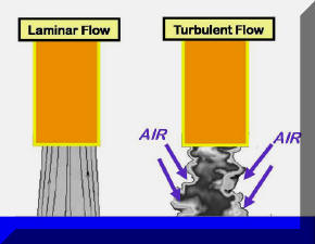 turbulent flow with any size gas cup. This causes air to
be pulled into the center of the shielding gas stream creating inferior weld
starts with excess spatter. This turbulent flow takes a short time to
stabilize into a more laminar, quality shielding gas stream even after flow returns to the normal
desired level. Therefore weld starts will contain entrained air in the
gas stream for several seconds even after the flow reaches the preset level. In
the February 2005 issue of Practical Welding Today magazine, Kevin Lyttle,
Manager Welding R&D for Praxair states; “In
many instances, production site surveys determine that shielding gas flow
rates typically are set in excess of 50 CFH. This can contribute to poor weld
quality as atmospheric gases are drawn into the arc zone because of excessive
gas turbulence. Optimized flow enhances quality and reduces shielding gas
usage.” turbulent flow with any size gas cup. This causes air to
be pulled into the center of the shielding gas stream creating inferior weld
starts with excess spatter. This turbulent flow takes a short time to
stabilize into a more laminar, quality shielding gas stream even after flow returns to the normal
desired level. Therefore weld starts will contain entrained air in the
gas stream for several seconds even after the flow reaches the preset level. In
the February 2005 issue of Practical Welding Today magazine, Kevin Lyttle,
Manager Welding R&D for Praxair states; “In
many instances, production site surveys determine that shielding gas flow
rates typically are set in excess of 50 CFH. This can contribute to poor weld
quality as atmospheric gases are drawn into the arc zone because of excessive
gas turbulence. Optimized flow enhances quality and reduces shielding gas
usage.”
|
|
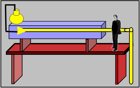 In
a 1893 technical paper Osborne Reynolds
discussed tests made that showed there was a very well defined flow level
below which a smooth "Laminar" flow was achieved. Beyond that level a
chaotic "Turbulent" flow exists. He also
defined if gas flow starts in a Turbulent mode, it takes time for it to become smooth and Laminar even when the velocity decreases.
Therefore at a weld start, the high velocity surge of shielding gas
exiting a MIG gun is Turbulent and will take some time to reach
the Laminar flow that is needed to eliminate air from the shielding gas
stream. We and others have measured the peak flow rate at over 200 CFH when Laminar flow requires flow rates of 55 CFH or less. Accompanying photo is a representation of Osborne Reynolds standing next to
his flow testing apparatus. In
a 1893 technical paper Osborne Reynolds
discussed tests made that showed there was a very well defined flow level
below which a smooth "Laminar" flow was achieved. Beyond that level a
chaotic "Turbulent" flow exists. He also
defined if gas flow starts in a Turbulent mode, it takes time for it to become smooth and Laminar even when the velocity decreases.
Therefore at a weld start, the high velocity surge of shielding gas
exiting a MIG gun is Turbulent and will take some time to reach
the Laminar flow that is needed to eliminate air from the shielding gas
stream. We and others have measured the peak flow rate at over 200 CFH when Laminar flow requires flow rates of 55 CFH or less. Accompanying photo is a representation of Osborne Reynolds standing next to
his flow testing apparatus.
|
|
PAST ATTEMPTS TO SOLVE SURGE PROBLEM AND
WASTE |
|
Restriction Orifices have occasionally been used to minimize the gas flow surge at the weld start. However,
assuming flow is still controlled at a regulator/flowgauge or flowmeter,
significant gas waste still exists! If a pressure gauge is put in the
shielding gas hose line the gas pressure changes observed are at similar
levels as if the restrictor was not present. Instead of the gas surge taking
about a second to occur it takes longer at a lower flow rate. Significant gas
waste occurs but over a longer time!
If the restrictor is used to control the steady state flow then
insufficient extra gas is available at each start to purge the MIG gun nozzle
and weld start area of moisture laden air. This causes similar problems
to those caused by the high surge flow!
See Why there is
a need for this extra gas and a special gas storage device defined by
Stauffer in his 1982 patented system. We have found welders see this
lack of extra gas to purge air at the start and increase the steady state flow in attempt to
compensate. This may help to some degree but can't offset the need
for enough gas to properly purge the weld start area. Two specific
observations at fabricators defined this problem. These observation
are
outlined below.
Flowmeters Placed at Wire Feeder Gas Inlet
were observed at a shop with 100 MIG welders. The fabricator had
moved the flowmeters to the inlet of the feeder from the pipeline gas
supply to reduce the gas surge at the weld start, which it did. The steady state
flow was observed on these welders during operation. About half were
set at 50 to 55 CFH, 25% were set near the top of the flow tube reading,
which was 70 CFH. The remaining 25% had the flow ball pinned to the
top. In our lab tests with this flowmeter we have found to
flow of 150 CFH with the needle valve fully opened! It appears the
welders were trying to compensate for the lack of the needed extra gas
flow at the weld start, wasting not saving gas!
Low Pressure Devices appear at first
to be a possible solution. However delivery systems have used pressures
of a minimum of 25 psi since the introduction of TIG and MIG for very good
reason. That is the minimum pressure needed to provide automatic
compensation of hose and MIG gun flow restrictions that occur in
production! We have measured changes in flow of 35% up to 65% in tests
with low pressure systems without any change in flow settings,
See Why.
Higher pressure also helps to quickly delivery some extra gas at the weld
start to purge the MIG gun nozzle and weld start area of moisture laden air.
|
|
PATENTED GAS SAVER SYSTEM
There is a simple way to significantly reduce MIG shielding gas waste due to
gas flow surge. First, employ a shielding gas hose with a much smaller
internal diameter/volume. At the low flow rates used for MIG and TIG welding this creates a
minimal and acceptable pressure drop. Secondly, incorporate a flow restriction orifice
on the wire feeder /welder end of the gas hose. This has the benefit of reducing
gas waste for very short time MIG gun trigger actuation such as when inching the
wire to cut off the end. The surge restricting orifice also
improves weld starts by minimizing turbulence of the shielding gas
stream. Note, a sufficient amount of extra shielding gas is still
available to quickly purge the weld start area and weld nozzle of moisture
laden air improving start weld quality.
|
|
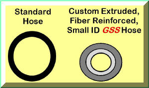
Patented
WA Technology Gas Saver System (GSSTM)
incorporates a
custom extruded, fiber reinforced, small ID hose
with a flow restrictor built into the hose connection at the wire feeder end.
The flow
 restrictor size is selected to
reduce the surge at the start but allow the operator to have full control of
the welding flow rate. It is also sized to allow a small amount of extra gas
flow to quickly purge air in the weld start area and which diffuses into the MIG gun
nozzle and gas line during the
stoppage. The
GSS
hose has a large OD and fiber reinforced construction to provide a
robust product which will not kink or flattened when stepped on. The hose volume is proportional to the
hose ID squared therefore it results in over a 4 fold reduction. The total %
reduction is calculated from this volume decrease and the small pressure drop
in the
GSS
hose and surge restrictor and exceeds 80%. This leaves sufficient extra gas to
quickly purge the weld start area at a limited maximum flow rate that
avoids excess turbulence.. restrictor size is selected to
reduce the surge at the start but allow the operator to have full control of
the welding flow rate. It is also sized to allow a small amount of extra gas
flow to quickly purge air in the weld start area and which diffuses into the MIG gun
nozzle and gas line during the
stoppage. The
GSS
hose has a large OD and fiber reinforced construction to provide a
robust product which will not kink or flattened when stepped on. The hose volume is proportional to the
hose ID squared therefore it results in over a 4 fold reduction. The total %
reduction is calculated from this volume decrease and the small pressure drop
in the
GSS
hose and surge restrictor and exceeds 80%. This leaves sufficient extra gas to
quickly purge the weld start area at a limited maximum flow rate that
avoids excess turbulence..
|
|
SOME
EXTRA GAS IS NEEDED AT THE WELD START
Just as the high gas
surge causes wasted gas; if gas flow control is attempted at the wire
feeder with an orifice, flowmeter or needle valve then the surge is
eliminated but now little or no extra gas is available at the weld start
to purge the MIG gun nozzle and weld start area of gas. We have found
in these instances welders raise the steady state gas flow in attempt to
compensate so they are not starting in air!
Check out the details of why this is
necessary. This creates considerable gas waste!
|
 WELDERS SETTING HIGH FLOWS? WELDERS SETTING HIGH FLOWS?
Are welders setting very high flow rates, wasting even more gas? We have measured flow rates from conventional flowmeters over 150 CFH when the needle valve was opened wide! The GSS will limit the maximum flow to the minimum turbulence level set by the included peak flow limiting orifice. This can be about half the level that can be set on a flowmeter. Note the orifice is not visible since it is in the barb end of the fitting on the wire feeder end.
|
|
SELECTION OPTIONS AND INSTALLATION
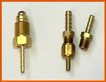 To gain the benefits of this patented system simply replace the existing gas
delivery hose from gas supply to welder or wire feeder with the WA Technology
GSS. For industrial MIG
systems hose end fittings are supplied with Compressed Gas Association (CGA) 032, 5/8 inch-18 male threaded
connectors (also called “B” size, left in below photo).
GSS
components and systems may be ordered in from 3 to 50 foot lengths. These
lengths are satisfactory with most commercial regulators or gas pipeline
pressures.
There are a number of fabricators using 100 foot or longer lengths however the
specific regulator/flowmeter
or gas pipeline pressure must be considered before ordering.
Email To gain the benefits of this patented system simply replace the existing gas
delivery hose from gas supply to welder or wire feeder with the WA Technology
GSS. For industrial MIG
systems hose end fittings are supplied with Compressed Gas Association (CGA) 032, 5/8 inch-18 male threaded
connectors (also called “B” size, left in below photo).
GSS
components and systems may be ordered in from 3 to 50 foot lengths. These
lengths are satisfactory with most commercial regulators or gas pipeline
pressures.
There are a number of fabricators using 100 foot or longer lengths however the
specific regulator/flowmeter
or gas pipeline pressure must be considered before ordering.
Email
For some feeders or regulators where a CGA fitting is not used, such as when a
hose barb is on the feeder or flow control device, the
GSS can be ordered with simple hose
splice connectors (right in photo). This allows the existing hose to be
cut close to the source and the
GSS assembly added by splicing to a
1/4 or 3/16 inch ID hose. Both systems incorporate a flow restriction
orifice on the end connected to the welder or feeder and perform the same.
|
|
TIG WELDING?
If you are TIG welding the
GSS
will also save you money, if your system incorporates a gas solenoid.
The gas surge at the weld start is significantly reduced in velocity to
improve shielding. That excess surge not only causes weld problems but
also pulls air into the gas stream potentially contaminating the tungsten
electrode making more frequent dressing needed.
CLICK TO SEE
a customer testimonial about our patented GSS
used for TIG Welding:
|
|
PRODUCTION RESULTS
A number of fabricators have performed total gas usage measurements comparing the
GSS
with a conventional delivery
hose. They reported savings in gas usage of from 30 to 63%. Many also
report welders are very impressed with the improved starts from the
significant reduction in initial gas flow peak surge.
 A fabricator of truck
boxes reported their test results with the GSS. They selected a repetitive
application, welding doors. Using a full cylinder with their standard gas
delivery hose they were able to fabricate 236 doors. With no other
changes than to replace the
gas
delivery hose with our
GSS
they welded 632 doors with a full cylinder of gas. That is a
63%
total shielding gas use savings! They immediately purchased 25 systems for all
their welders. Two years latter they added 10 more MIG welders and called
and asked for 10 more “Magic Hose!” A fabricator of truck
boxes reported their test results with the GSS. They selected a repetitive
application, welding doors. Using a full cylinder with their standard gas
delivery hose they were able to fabricate 236 doors. With no other
changes than to replace the
gas
delivery hose with our
GSS
they welded 632 doors with a full cylinder of gas. That is a
63%
total shielding gas use savings! They immediately purchased 25 systems for all
their welders. Two years latter they added 10 more MIG welders and called
and asked for 10 more “Magic Hose!”
This
production example shows why extra gas at the weld start can reduce gas
use. Welders at
a Bar Joist fabricator wanted more gas flow than the 45 CFH that was set
with the orifices installed at their feeders. In some
instances they were drilling the orifice to achieve more gas flow. A
GSS
was installed with gas control at the pipeline drop. This provided a controlled amount of extra gas at the weld
start. By providing extra gas at the start the
GSS
was able to improve starts and the steady state flow could be reduced to
35 CFH or less and the welders still saw a significant improvement!
That was because the same amount of extra gas was still provided at the
weld start. Overall gas
savings were documented at 30+% and most important - welders were
pleased with the improved weld performance because extra start gas quickly
purged the weld area of air!
Check out the details.
See Specifics of 16 Case Histories |
|
BOTTOM LINE
The
WA Technology
GSS
has no
moving parts to wear, repair or leak; no pressures to set or knobs to adjust.
It’s unique, patented design maintains the gas pressure in the delivery hose.
This allows a small amount of extra gas to quickly flow at the weld start to purge air and moisture in the weld zone.
It also purges air that enters the MIG gun shielding gas
nozzle,
MIG gun body and cable during each weld stoppage.
Maintaining the higher pressure also retains the systems ability to
automatically compensate for varying pressure drops in the MIG system as
spatter builds in the nozzle, may partially clog the gas diffuser and is
restricted as the small gas passage in the gun cable is bent, etc. These
flow restrictions are automatically
compensated to maintain the preset flow. That is a key reason regulator
flow systems are designed to operate at higher pressures. Want to
understand why high pressure regulator/flowmeters are
"A Good Thing?" Click Here. The
GSS
does not interfere with the welders ability to adjust the shielding gas flow
within any reasonable flow level desired. If they are setting very high gas flow rates that also causes air to be pulled into the gas stream, the GSS will limit flows to a minimum turbulence level.-saving more gas.
The
GSS hose is
made with a heavy wall thickness and with fiber reinforced construction to
provide a robust product. It will continue to flow even when stepped on. The
heavy wall thickness makes the hose resistant to leaks caused by abrasion.
For most
applications the
GSS
will pay for itself in gas waste reduction alone in a matter of weeks.
The improved weld starts and the reduced cylinder handling are added benefits
which may be more important in some applications.
The system
is backed with a money back guarantee.
|
|

A Message from the President of
WA Technology (Who was the 2007 President of the 75,000
Member American Welding Society)
Click to See |
Sales Literature
PDF File for
Downloading,
Click on ICONS
Technical Paper
"MIG GAS CONTROL" |
|


