 THE EFFECT OF
PRESSURE ON GAS VOLUME
THE EFFECT OF
PRESSURE ON GAS VOLUME
Consider an
Argon gas cylinder. One holding 310 Cubic Feet (CF) of Argon [measured
at Standard Temperature and Pressure (STP); that's what you paying for] has only
1.8 CF of physical internal volume. How does it hold all that gas?
Because of the increased pressure over atmospheric.
The volume of gas
in the cylinder at STP is directly proportional to the absolute pressure.
At 2500 psi = 2514.7 psia (psia = absolute pressure.
That is the gauge reading +14.7 psi at sea level.) Therefore the volume will be 2515 / 14.7 or
171 x 1.8 (physical volume) CF =
310 CF of gas at STP.
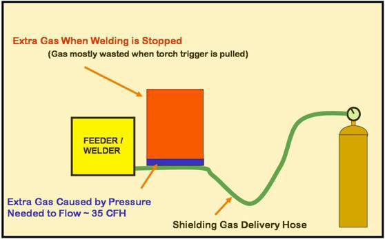
Therefore when
welding stops and the gas solenoid is closed the shielding gas delivery hose is
quickly pressurized to regulator or pipeline pressure. It holds
much more gas than
the actual internal physical volume of the hose. How much more depends on the pressure.
Typical flowmeter and flowgauge regulator pressures range from 25 to 80 psi
and as do typical pipeline pressures.
To reach
80 psi there must be 6.4 times the amount of gas in the hose then when the
gauge pressure is zero! (The calculation is (80 psi+14.7 psi)/ 14.7
psi = 6.4. That extra gas blasts out when welding starts or anytime
the torch trigger is pulled even if only inching the wire to cut off the
end! NOTE: PRESSURE CAN NOT INCREASE UNLESS THE AMOUNT OF GAS IN THE
HOSE INCREASES.
Interesting Facts:
1)
At full cylinder pressure Argon is still a gas but it's actually pretty heavy!
(310 CF weights about 31 pounds.) When the gas is contained in the 1.8
CF cylinder it's about 30% the density of water!
2) Another fact to give perspective on how
far apart gas atoms are at 75 F and atmospheric pressure; for Argon gas they
are 845 times further apart then when in Liquid Argon! Doesn't take
much pressure to get them 6 times closer!


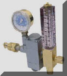 Flowmeters
 or orifices
used on pipelines also allow gas to flow until it reaches pipeline pressure when welding stops. A typical pipeline pressure
is 50 psi.
or orifices
used on pipelines also allow gas to flow until it reaches pipeline pressure when welding stops. A typical pipeline pressure
is 50 psi.  Hose expansion
also has an effect on the extra volume of stored gas
when welding stops. Making measurements of a relatively heavy wall
(0.093 inch wall, 1/4 inch ID) commercial gas delivery hose we obtained the
following data:
Hose expansion
also has an effect on the extra volume of stored gas
when welding stops. Making measurements of a relatively heavy wall
(0.093 inch wall, 1/4 inch ID) commercial gas delivery hose we obtained the
following data: