Response to an inaccurate Forum comment about
pressure drop in MIG shielding gas hose: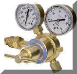
First lets set the record
straight. Your setting flow NOT pressure on your MIG flowmeter even on a regulator/flowmeter (Pictured Right.) Look carefully and
you'll see the output gauge says CFH NOT psi. What does that
mean? CFH stands for Cubic Feet per Hour. That is what your
setting. Pressure is measured in Pounds per Square Inch (psi.)
A point of confusion on
required hose size may come from what is needed with an air compressor.
Even a small air compressor may be rated at 10 CFM and does need a large hose!
That stands for Cubic Feet per Minute! So even a small air compressor
can flow 10 CFM x 60 min/hr or 600 CFH!! Sure, at that flow rate you
need a big hose! But not at the 25 to 30 CFH used in MIG welding.
That flow rate is only 1/2 CFM (30 CFH / 60 min/hr!) Pretty low flow. In fact that is about your breathing
rate! Anything much more and air is just being pulling into
the gas stream due to turbulence!
At 25 to 30 CFH flow rate with
a 25 foot
GSS
hose there will be about a 2 psi pressure drop. In a 1/4 inch hose it
is hardly measurable!
The person recommending a 3/8 inch hose was
indirectly also telling them to waste 2.25 time more gas at each weld start! How
can that be? The physical volume of a hose is proportional to the
diameter squared. Therefore a 3/8 inch hose will hold (3/8)2 / (1/4)2
= 2.25 times more gas volume than a 1/4 inch hose every time welding stops. If your using a
regulator/flowgauge, like the one in the above picture, you'll have plenty of excess
pressure. Defining how the system works so you'll see why:
With a
regulator/flowgauge you're actually setting pressure! Your setting
the pressure above a very small orifice in the outlet of the regulator.
Typically the orifice is about 0.025 inches. It takes about 40 psi above the
small orifice to flow 25 CFH. Why do they have such high pressure?
So the flow will be constant when spatter builds in the gun nozzle and as you bend
the small MIG gun cable gas passage.
Typically the pressure needed at the inlet to a
welder/feeder is 3 to 7 psi and vary was you weld and the cable is bent etc. By having about 40 psi above the small
orifice the flow will remain at the flow you set.
(SEE
Automatic Flow Compensation if you want to know how that works.)
If you put a
pressure gauge between the welder/feeder and the gas delivery hose you'll
measure about that 3 to 7 psi when your welding. However when welding
stops, gas will still flow through the small orifice and will rise quickly
to the 40 psi regulator pressure. (Note, if using a pipeline gas supply
and a flowmeter or flow control orifice it will quickly reach the pipeline
pressure.) That creates excess stored gas and the big surge of gas at the
weld start which is what our
GSS
eliminates!
Now if you read about
Automatic Flow Compensation you found twice the pressure was
needed above that small orifice compared to below it to achieve that constant flow. (Note, all
pressures measured a absolute pressure which equals gauge pressure +
atmospheric pressure, nominally 14.7 psi.) With 25 feet of our
GSS
hose with its ~2 psi
pressure drop you have more than sufficient pressure with even 25 psi to achieve constant
flow.
Probably just provided more
information than you
wanted to know but if you have any questions Email:
TechSupport@NetWelding.com


 The typical 1/4 inch ID hose causes excess
gas to be stored in the hose every time welding stops. The stored
excess
gas blasts
out and is wasted at every weld start (or even when inching the wire to position in the joint or
to cut off the end!) Fabricators find it causes from 30 to over 60% wasted
gas!
The typical 1/4 inch ID hose causes excess
gas to be stored in the hose every time welding stops. The stored
excess
gas blasts
out and is wasted at every weld start (or even when inching the wire to position in the joint or
to cut off the end!) Fabricators find it causes from 30 to over 60% wasted
gas!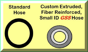
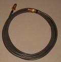
 The
patented
GSS employs unique components allowing it to utilize
a small ID gas delivery hose for MIG (and TIG) welding. To handle the
rugged environment the custom extruded hose has a very heavy wall. It
is also fiber reinforced so it will not wear through even when dragged on
the shop floor. The large OD to ID ratio prevents the gas from being
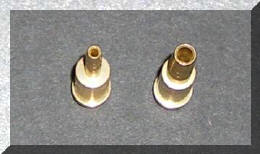
blocked even when the hose is stepped on. The CGA fittings can not be
made from large ID heavy wall brass tubing as can 1/4 inch hose fittings.
This makes them more difficult and costly to manufacture. The cost is
more than twice the more common 1/4 inch hose barb fittings. The
accompanying photos provide a comparison between these two CGA hose barb
sizes.
The
patented
GSS employs unique components allowing it to utilize
a small ID gas delivery hose for MIG (and TIG) welding. To handle the
rugged environment the custom extruded hose has a very heavy wall. It
is also fiber reinforced so it will not wear through even when dragged on
the shop floor. The large OD to ID ratio prevents the gas from being
blocked even when the hose is stepped on. The CGA fittings can not be
made from large ID heavy wall brass tubing as can 1/4 inch hose fittings.
This makes them more difficult and costly to manufacture. The cost is
more than twice the more common 1/4 inch hose barb fittings. The
accompanying photos provide a comparison between these two CGA hose barb
sizes.
