| Summary
of Gas Saver System |
GAS WASTE PROBLEM:
Two recent publications quote knowledgeable welding authorities indicating the
average user of MIG welding consumes from 2 1/2 to 6 times the amount of
shielding gas they could or should use.
CHECK REFERENCES
|
|
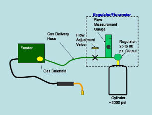
REASON FOR GAS WASTE:
A
key reason for the shielding gas waste is the buildup of excess gas
in the delivery hose when welding is stopped. The amount of excess is
dependent on the pressure in the gas delivery hose when welding is stopped versus when
welding. When welding the pressure in the gas delivery hose is reduced
by the needle valve or orifice to 3 to 7 psi. When welding stops it rises to
the regulator or pipeline pressure up to 80 psi. This excess gas is expelled
every time welding is started or when just inching the wire to cut off the end.
Depending on the regulator/flowmeter or pipeline pressure, the volume wasted can exceed 5 times the hose volume when measured at standard pressure and temperature. For relatively short welds, the
waste can easily exceed the amount used when welding. Longer gas delivery hoses
waste more gas. CHECK
REFERENCES.
However you need relatively
high pressure to provide Automatic Flow Compensation. That's why gas
distribution systems are designed that way? What more information on this
feature?
|
|
 STARTING PROBLEMS: STARTING PROBLEMS:
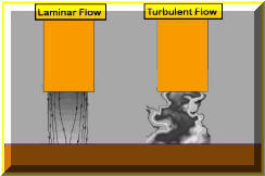
In
addition to the excess gas being wasted, the flow rate is so high at the weld
start it creates turbulent shielding gas flow. This causes air
(with its combined moisture) to be pulled into the shielding
gas stream creating poor starts with excess spatter and possibly weld porosity.
Even with relatively short, conventional gas delivery hoses this turbulent flow
is created at the weld start. A production example where this problem existed and was
solved with a Gas Saver System is sited. CHECK IT OUT. |
|
SIMPLE SOLUTION:
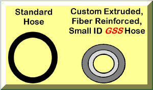
A
simple way to reduce the gas waste without reducing system pressure is to reduce
the hose volume (This
maintains automatic flow compensation
and quickly delivers a controlled amount
extra shielding gas to
displace air in the weld start zone and torch).
A special small ID hose is used with the patented Gas Saver System (GSSTM)
that eliminates the excess "gas blast" at each weld start. Since gas velocity would still be excessive at
the start, a restriction orifice is incorporated into the hose fitting at the
feeder end. The restriction orifice further reduces gas waste.. Sufficient extra gas is left to quickly purge the air
from the torch and weld zone. The surge restrictor size is selected to allow any normal gas
flow setting. This hose is custom extruded with a large OD and fiber
reinforcement to meet the tough physical needs of the environment. It can
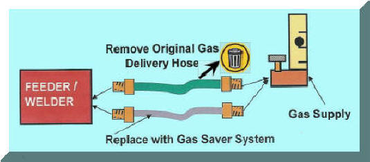
be stepped on without altering flow. If you have a Miller, Lincoln, ESAB,
or Hobart welder a simple prefitted system is available. Just remove the
existing hose and screw in the GSS. |
|
PROBLEMS WITH PAST SOLUTIONS:
Restriction orifices
have been added at the wire feeder to reduce gas
surge velocity. Most of these are sized to restrict the flow to some
maximum level but still allow the welder to adjust flow rates. This does
help with the weld start problem -however- the pressure still builds in the gas
delivery hose to that in
the pipeline or regulator when welding is stopped. When welding is started
most of the excess is wasted, it just takes longer for the waste to occur,
perhaps several seconds making it less obvious!
If the orifice is added at the feeder and is sized to control flow, several
problems exist. A production example of one of those problems,
lack of
extra gas at the start, is detailed in
Production Results.
CHECK IT OUT. This
problem will exist with any device controlling flow at the feeder. Also if the
orifice size is selected to allow only a small amount of gas flow and since it provides no
extra gas at the start, welders frequently drill them out to get more flow.
However the smallest drill often available is 1/16 inches. Sounds small
enough, but on a 50 psi gas pipeline that produces 165 CFH gas flow!!
Low pressure devices have also been employed to reduce starting surge.
These can produce several problems depending how they are implemented.
Similar to the use of orifices, they may save only a small amount of waste.
Or they may not allow enough extra gas at the weld start to displace air that
enters into the torch and cable when welding is stopped or to quickly displace
air (with its combined moisture) in the weld start zone. Perhaps the
biggest problem with low pressure devices is they do not provide automatic compensation of flow rate
inherent in higher pressure systems.
Want to understand why
high pressure regulator/flowmeters are
"A Good Thing?"
CHECK
IT OUT
How Does Automatic Flow Compensation
Work?
Manufacturer of Low Pressure Device Even Warns of Possible Problems. See Published Information.
For Recommended Gas
Delivery System for Optimum Performance-CLICK |
| BENEFIT SUMMARY: |
|
The
patented
WA Technology
GSS::
-
Has
no moving parts to wear, repair or leak;
-
Has no pressures to set or knobs to adjust.
-
Allows a
small amount of extra gas flow at the weld start to quickly purge air (with
its combined moisture) in the weld zone and air that enters the torch
shielding gas cup, torch body and cable during weld stoppage.
-
Unique, patented design reduces gas waste
due to start surge by about 80% while maintaining the gas pressure in the delivery hose.
If welders are setting very high gas flow rates, wasting even more gas, the GSS will limit flow settings to any reasonable, non-turbulant level. We have found some flowmeters will flow ~150 CFH with the neelde valve wide open, the GSS will allow only about half those levels.
-
Maintaining the higher pressure retains the systems ability to automatically
compensate for varying pressure drops in the delivery hose when inadvertently
pinched, squeezed, bent, etc. Pressure drops in the torch due to
conduit bending and spatter buildup in the front end are also automatically
compensated to maintain the preset flow. That is a key reason regulator flow
systems are designed to operate at these pressures from the time MIG and TIG
welding were introduced in the 1950's!.
-
The
GSS
is inexpensive, payback is measured in weeks.
|
|
Saving Shielding Gas and Improving Weld
Start Quality is Easy..
"JUST"
 |
 |
PURCHASE
PRODUCT |
|
Want More Information About the Gas
Saver System ? |
|
What Are Gas Costs as a Percent
of Total Weld Cost? |
| Review Fabricators Results
with the .GSS |
|
Questions
About Installation? |
| Want
More Control of the Maximum Allowable Flow Rate? |

Free Technical Paper, "MIG
SHIELDING GAS
CONTROL"
CLICK ICON for PDF DOWNLOAD |


