Installing the Gas Saver System (GSSTM) Is Simple.
See Schematic and Details Below:
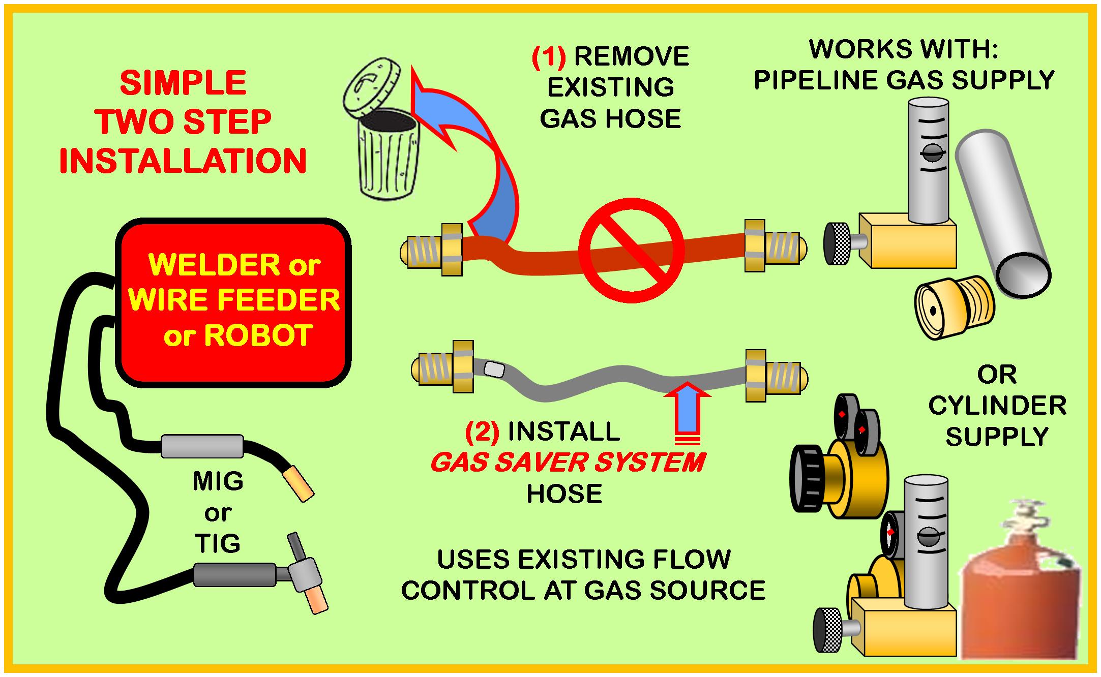
Over 15,000 in Use in Industrial Shops- Many in Small and Home Shops
Also Effective for TIG Welders-CLICK
Have a different configuration?
Email: TechSupport@NetWelding.com
|
|
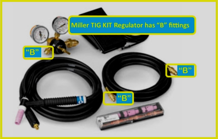
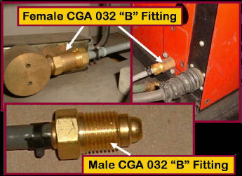 Most US
produced welders and wire feeders by Lincoln, Miller, Hobart, L-TEC
and ESAB have Female Compressed Gas Association (CGA)
"B" inlet gas fittings Female CGA "B" fittings are also on the output of most US produced shielding gas regulator
flow controls and flowmeters. Most US
produced welders and wire feeders by Lincoln, Miller, Hobart, L-TEC
and ESAB have Female Compressed Gas Association (CGA)
"B" inlet gas fittings Female CGA "B" fittings are also on the output of most US produced shielding gas regulator
flow controls and flowmeters.
Our standard patented Gas Saver System (GSS) comes with the male counterpart CGA 032 "B" fitting installed on both ends.
Simply unscrew the existing shielding gas delivery hose and screw in the GSS.
Pictures above left show a GSS installed on a Lincoln and another on an ESAB
industrial wire feeder. It simply
screws into the female connector on the back.
See notes and pics below about recently purchased Hobart Handler and Miller 211 welders (both ITW companies as is Smith gas controls.) They have female "B" fittings on the welders BUT one piece hose barb/flow control fittings on the regulator/flowgauge. These less expensive, small shop welders are using a cheaper fitting approach employed in Asia where the regulator fitting incorporates a very small orifice to set flow rate. This is similar to some regulators and welders sold by Harbor Freight, sourced in China and many others like Chicago Electric, Everlast, Longevity and a number of others that source the welder and flow control regulators from overseas. Unlike Miller and Hobart welders that use CGA "B" fittings on the welder, both welders and gas regulators on many products coming from Asia need "splice fittings" on both ends. We added a new part number WAT-FS4 that is 4 feet long and has Splice Fittings on both ends. It is universal and can fit almost any welder and regulator flow control no matter what exiting hose connections are used. It can be ordered with a simple CLICKl
Note: We have recently found two piece fittings on an Eastwood 135 MIG welder that in fact has two piece fittings that do mate with our US manufactured "B" fittings. Tests showed that our "B" fittings fit their product providing leak free connections. They are two piece fittings with a rounded metal seat. A recent check of some regulator/flowmeters from Harbor Freight also had two piece "B" fittings. They looked slightly different with a small flat on the tip, but the mating gas sealing surface is above that in the rounded area.
Saw a similar regulator/flowgauge shielding gas regulator for sale at Harbor Freight
No problem fitting a GSS to any length hose needed for welders or regulator flow controls with different fittings on one end. Just Email and ask for a Splice Fitting on the hose end needed. The price and performance are the same. We have sold thousands of GSS's to industrial fabricators in China, Europe, Saudi Arabia, Mexico, etc with Splice Fittings!
The following are examples of GSS's on smaller size welders: |
|
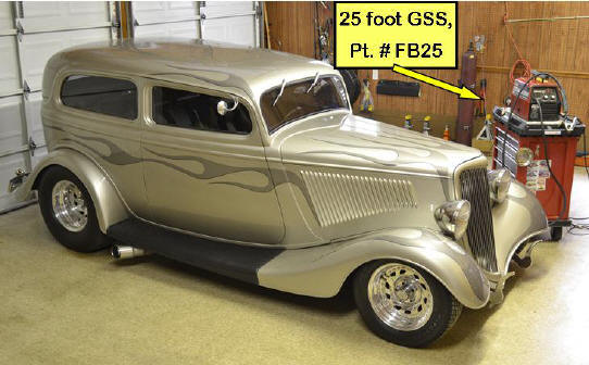
A 25 foot long GSS (Part # FB25)
is used in my Home Shop with a large gas cylinder chained to one wall and
welder on a movable work cart.
Longer systems can be supplied if needed. The 160 cubic foot cylinder
is the largest my local distributor offers for sale versus renting.
See Perry Thomasson's home shop and comments about
his 50 foot long GSS. |
|
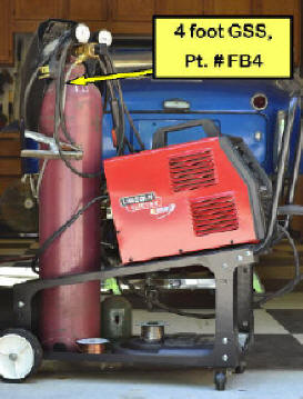 This Lincoln
180 amp Welder uses a 4 foot GSS (part #; FB4) to
reduce gas usage and improve weld start quality. This Lincoln
180 amp Welder uses a 4 foot GSS (part #; FB4) to
reduce gas usage and improve weld start quality.
It is simple to install; just unthread existing gas delivery hose from flow
control setting regulator/flowgauge to welder and screw in
GSS which comes with the same
industry standard CGA 032 "B" male fittings.
One end of
GSS has a Mylar label indicating it screws into
feeder-welder. The fitting on that end contains a peak flow rate limiting orifice.
With the many
short welds and tack welds made in home shops the gas cylinder will last
more than twice as long and give twice the warning of running out. A
major benefit on a weekend!
Note: All Lincoln welders and supplied regulator/flowgauges use "B" fittings at both ends. At least those we have seen to-date. |
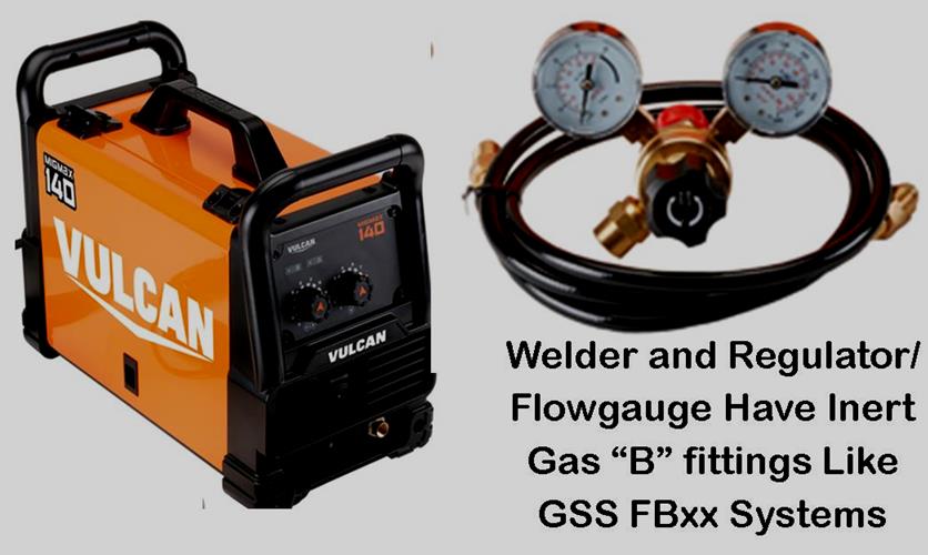 Harbor Freight's New Vulcan (and Titanium) Series MIG and TIG Welders use Inert Gas "B" Fittings as supplied with our GSS FBxx products. Harbor Freight's New Vulcan (and Titanium) Series MIG and TIG Welders use Inert Gas "B" Fittings as supplied with our GSS FBxx products.
Simply order an FB3, FB4, FB6 etc (the number refers to the length in feet) needed and you'll reduce your SHIELDING GAS USE BY HALF or more AND IMPROVE YOUR WELD START 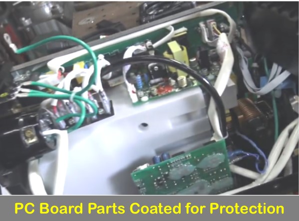 QUALITY! QUALITY!
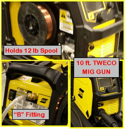
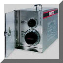
Reports indicate the Vulcan quality and performance are very good. The pic right is the internal parts. It's very well constructed with quality components. Critical areas on the printed circuit boards are coated to protect them from the environment.
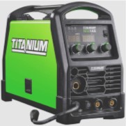
Harbor Freight Titanium Brand Welders also use threaded CGA "B" gas hose fittings. Order the GSS FB3, FB4, FB6, whatever length needed. |
 ESAB's NEW REBEL: Had a chance to weld with the new ESAB Rebel. This light weight powerful welder has many features formerly only available in much more expensive machines. It operates on either 120 or 230 volt input. Has a max capacity of 240 amps and welds in the MIG, DC TIG and Stick mode! In the MIG mode it has an automatic setting circuit that adjusts the volts and inductance to provide the optimum "Short Arc." In the past it took years to develop that skill which minimizes spatter and reduces the chance of cold welds or "cold laps." ESAB's NEW REBEL: Had a chance to weld with the new ESAB Rebel. This light weight powerful welder has many features formerly only available in much more expensive machines. It operates on either 120 or 230 volt input. Has a max capacity of 240 amps and welds in the MIG, DC TIG and Stick mode! In the MIG mode it has an automatic setting circuit that adjusts the volts and inductance to provide the optimum "Short Arc." In the past it took years to develop that skill which minimizes spatter and reduces the chance of cold welds or "cold laps."
I found it had an interesting feature that helps improve arc striking that was only available in very expensive MIG robot welders. It prevents a ball from forming at the wire end when stopping. A very fine point remains that makes arc striking for the next weld easy. At ~$1500 on the Net, a great value.
Found it needed only one thing - you guessed it - a GSS to improve weld start quality and save gas! The Rebel welder and the supplied Victor cylinder regulator/flowmeter both have "B" fittings so just order the FBXX of the length you require.
 Lincoln Power MIG 210 Lincoln Power MIG 210
Lincoln has also introduced a similar welder to the ESAB Rebel. It's also light weight with high capacity that can operate with 120 or 220 volt input. Like the ESAB and like most other Lincoln MIG /TIG welders and cylinder flow control regulators they both use "B" fittings.
Just like the ESAB welder, it needs a GSS! |
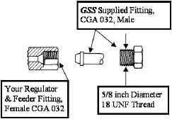
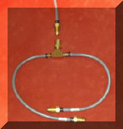
Sketch on right shows the CGA "B" fitting connections. Male CGA "B" fittings
are supplied on
both ends of the GSS hose. Prefitted
GSS
FB3, FB4, FB6, FB12, FB25 use this connector
Note, these are precision machined parts. These are also NOT tapered pipe threads so Teflon tape etc SHOULD NEVER BE USED. The threaded section only presses the precision brass seats together to provide an easy to disconnect gas tight connection.
As mentioned we have recently found two piece fittings on an Eastwood 135 MIG welder that do mate with a gas tight seal with our US manufactured "B" fittings. A check of some regulator/flowmeters from Harbor Freight also show they have two piece "B" type fittings. They looked slightly different with a small flat on the tip, but the mating gas sealing surface is in the rounded area. |
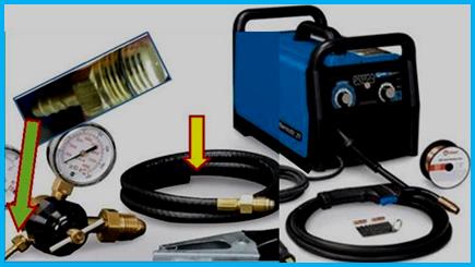
Two Solutions for Wire Feeder/Welder/Robot or Gas Supply
That Has a Hose Barb
or a Hose Comes Out of the Welder:
|
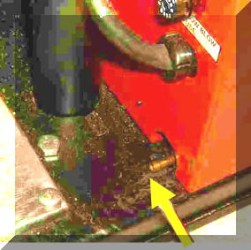
The wire feeder shown at left has a hose barb connector to
attach the shielding gas delivery hose (see yellow arrow.) This may
also be an internal connection with the hose simply exiting the case of the
feeder or welder. It
could also be a quick disconnect fitting or anything other than a CGA 032, "B"
fitting.
There are two methods of installing the GSS
in these situations or where the feeder may have a CGA 032 "B" connector
but the gas supply does not.
Method 1 costs the same as our standard "B" fitting hose. We will just supply a splice fitting on the hose end requested. Many welders made overseas, i.e. Harbor Freight, Chicago Electric, Northern Tool, Everlast, Longevity, Forney, etc. For these welders, check the fittings on each hose end. If they are not made in two pieces or have a tapered pipe thread or are a simple hose barb; you'll need a splice fitting.
|
| Either of the Following Two Installation Methods Can Be Used When a CGA Female "B" Fitting is NOT on One or Both Ends. Both perform Equal to a GSS with CGA "B" Fittings: |
Installation Method 1
We Can Provide
the GSS
with Splice Fittings at
the Same Price as CGA Fittings (Photo Below Right.)
Instead of supplying two CGA
032, "B" fittings on the GSS (for
example, if your
welder or MIG welding robot has a hose barb or other fitting and your regulator/flowgauge uses a CGA 032 female
"B" fitting) we
will install a Splice Fitting 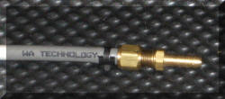 on the hose end where you do not have a female
CGA 032 "B" fitting.
You just cut the existing hose close to the feeder/welder or gas regulator/flowgauge
and insert the hose barb at the end of the GSS
and tighten the supplied screw clamp. The price
will be the same as a fitted hose with CGA fittings, i.e. order a FB3,
FB4, FB6,
FB12 or FB25 and send an Email about the special need JUST CLICK TO SEND EMAIL when you place your order and let us know WHICH END or if BOTH
need Splice Fittings. NOTE: the fitting on the feeder/welder end
incorporates a surge limiting orifice so we must know which end will have
the Splice Fitting. Include you're shipping address so we can
match your Email with the PayPal order. on the hose end where you do not have a female
CGA 032 "B" fitting.
You just cut the existing hose close to the feeder/welder or gas regulator/flowgauge
and insert the hose barb at the end of the GSS
and tighten the supplied screw clamp. The price
will be the same as a fitted hose with CGA fittings, i.e. order a FB3,
FB4, FB6,
FB12 or FB25 and send an Email about the special need JUST CLICK TO SEND EMAIL when you place your order and let us know WHICH END or if BOTH
need Splice Fittings. NOTE: the fitting on the feeder/welder end
incorporates a surge limiting orifice so we must know which end will have
the Splice Fitting. Include you're shipping address so we can
match your Email with the PayPal order.
Need a Larger Hose Barb?
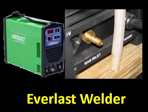 Mike Buehner recently said they needed a larger hose barb for his EVERLAST Welder. If you require this for a larger hose ID, we can supply one or both ends of a GSS hose with a 5/16 inch hose barb. He bought two GSS's for his MIG and TIG welders and our portable flowmeter (PFM.) Mike Buehner recently said they needed a larger hose barb for his EVERLAST Welder. If you require this for a larger hose ID, we can supply one or both ends of a GSS hose with a 5/16 inch hose barb. He bought two GSS's for his MIG and TIG welders and our portable flowmeter (PFM.)
Mike reported the results: "On my MIG welder using the GSS, I no longer get a huge surge of gas when starting the weld and the shielding is much better producing far improved looking welds. In conclusion, I have significantly better welds using your portable flowmeter (PFM) and the GSS system so I know exactly what the gas flow is at the torch and have much less gas burst at weld initiation. I used to take shielding gas flow for granted before looking at your products! I guess I didn't know what i didn't know! Thanks for your emails and fast shipping of good products. Count me as a happy customer!
(NOTE: Mike also indicated he downloaded and read the PDF "MIG FLOW CONTROL" available on the top of every web page.)

|
Hobart Handler & Miller 211
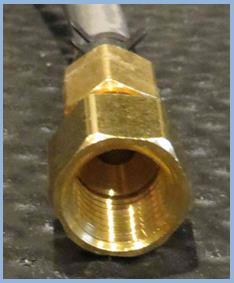
Jason Insley purchased a Hobart Handler that included a Smith 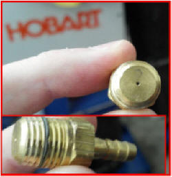 Regulator/Flowgauge.
The welder had a female CGA 032 "B" fitting but the gas Regulator/Flowgauge
had a hose barb fitting. Jason removed the barb fitting and although it had
a thread that looked similar to a CGA "B" fitting thread ( is not, it is
a pipe tread.) He found, as
expected, it had a flow control orifice built into the hose barb fitting
inlet! See the top left photo Jason sent. This must remain in place to
properly control flow. Jason ordered our part number FB3 (3 foot GSS.) In an Email he requested our standard CGA 032 "B" male fitting on
the welder end and a Splice Fitting on the regulator end.
Jason Emailed the pictures left and commented: "Everything work fine. And my weld starts have definitely improved since
installing the GSS. Thanks again." Regulator/Flowgauge.
The welder had a female CGA 032 "B" fitting but the gas Regulator/Flowgauge
had a hose barb fitting. Jason removed the barb fitting and although it had
a thread that looked similar to a CGA "B" fitting thread ( is not, it is
a pipe tread.) He found, as
expected, it had a flow control orifice built into the hose barb fitting
inlet! See the top left photo Jason sent. This must remain in place to
properly control flow. Jason ordered our part number FB3 (3 foot GSS.) In an Email he requested our standard CGA 032 "B" male fitting on
the welder end and a Splice Fitting on the regulator end.
Jason Emailed the pictures left and commented: "Everything work fine. And my weld starts have definitely improved since
installing the GSS. Thanks again."
Need a Splice
Connection on
either end? Just Email what you need when you place the order. A
splice connection can be placed on either or both ends for the same price. The
one on the welder end has the same peak flow, surge limiting orifice as the
"B" fitting.
Performance is identical. |
Miller 211 MIG Welder
 Newly purchased Miller 211 welders, are the same as the Hobart Handler (both ITW companies) and come with a Miller labeled regulator/flowgauge that had a hose barb as part of a one piece fitting (Green arrow pic left. Note a customer reported it was labeled Made in China, which explains the hose barb as many foreign made welders DO NOT use the US Compressed Gas Association (CGA) metal to metal seat fittings!) The suppled hose had no fitting on one end (Yellow arrow) so it could be inserted onto the supplied regulator/flowgauge hose barb. Like the Handler, it is NOT a CGA "B" fitting. Miller 141 and 215 welders use the same Regulator/Flowgauge with a hose barb outlet. Newly purchased Miller 211 welders, are the same as the Hobart Handler (both ITW companies) and come with a Miller labeled regulator/flowgauge that had a hose barb as part of a one piece fitting (Green arrow pic left. Note a customer reported it was labeled Made in China, which explains the hose barb as many foreign made welders DO NOT use the US Compressed Gas Association (CGA) metal to metal seat fittings!) The suppled hose had no fitting on one end (Yellow arrow) so it could be inserted onto the supplied regulator/flowgauge hose barb. Like the Handler, it is NOT a CGA "B" fitting. Miller 141 and 215 welders use the same Regulator/Flowgauge with a hose barb outlet.
NOTE: that compares to older Miller 211's and most other Miller welders that have screw in metal to metal seal "B" fittings on both hose ends. They came with a Smith Regulator/Flowgauge (also an ITW company) but a customer his Hobart Handler regulator/flowgauge had a "Made in China" label! That explains the regulators low cost hose barb outlet versus the more 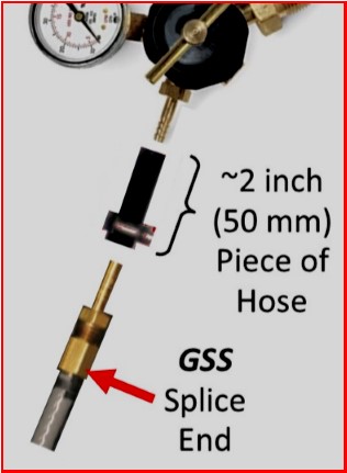 expensive, metal to metal seat CGA "B" fitting! I find it ironic that Harbor Freight;s latest inverter based welders from China (Vulcan and Titanium) now come with a CGA "B" fitting and Miller is buying regulators from China with their old "cheap" hose barb outlet! LOL expensive, metal to metal seat CGA "B" fitting! I find it ironic that Harbor Freight;s latest inverter based welders from China (Vulcan and Titanium) now come with a CGA "B" fitting and Miller is buying regulators from China with their old "cheap" hose barb outlet! LOL
Although that regulator hose barb fitting is threaded, it is a pipe thread NOT a straight thread like the "B" fitting that just tightens a metal to metal gas seat seal. The solution is to order the FBS4 GSS from the order page, or send an Email and request a splice fitting on the gas supply end. We'll send the GSS with a hose barb connected to that end. Then simply cut the existing hose close to the exiting fittings and insert the one supplied with the GSS. 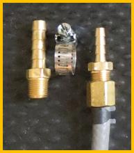 The Miller 211 welder (as all Miller welders) does use a CGA female "B" bulkhead fitting so our "B" fitting fits that end. The Miller 211 welder (as all Miller welders) does use a CGA female "B" bulkhead fitting so our "B" fitting fits that end.
Using a hose barb approach can be employed with welders and regulators coming from Asia and Europe that often use a simple hose barb. No problem for a GSS, splice fittings are what we supply when selling outside the US and Canada. We can supply a hose barb on both ends that fits any hose sizes used.
You can order our part number FBS4 (see GSS Purchase Page) that has a "B" fitting on the welder end and a splice fittings on both hose ends.
Note Miller Welders that use a hose barb fitting for the MIG Regulator/Flowgauge when equipped with a TIG KIT may have a Regulator/Flowgauge with a more conventional Regulator/Flowgauge that uses a CGA "B" outlet fitting.
 Since pure Argon is used with TIG a separate cylinder Regulator/Flowgauge may be desired BUT is not essential. The same inert gas Regulator/Flowauge can be used for pure Argon and Argon CO2 gas mixtures. Since pure Argon is used with TIG a separate cylinder Regulator/Flowgauge may be desired BUT is not essential. The same inert gas Regulator/Flowauge can be used for pure Argon and Argon CO2 gas mixtures.
Check the outlet to see what is needed fro your application. An EASY way to check is to take the fitting on the MILLER welder (since all use CGA "B" fittings and see if it fits the Regulator/Flowgauge. If it does order any length FB GSS desired,
Still Have A
Question About The Fittings Needed?
Perhaps this
picture will help.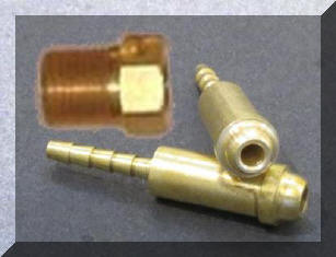
The picture
shows two CGA 032 "B" fittings at different angles. Note the ends
have
a rounded shape. It matches the precise shape of the female fittings that are
on most US manufactured MIG and TIG welders and MIG wire
feeders. A female CGA 032 "B" fitting is also used on the outlet of
most US made Regulator/Flowmeters, and Regulator/Flowgauges. Note, the
nut is separate and it Does NOT have a tapered pipe tread. It
has a straight thread and only tightens the hose barb end against the mating metal seat in the
female fitting on the welder, feeder and gas supply. If the fitting on your welder or
regulator is one piece, i.e. with barb and nut together, like the one that came
with the Hobart Handler, Miller 211 regulators above or those sold by Harbor Freight made in China, it is NOT a CGA fitting so a Splice
Fitting should be ordered for the gas supply GSS hose end.
Email If You Still Have a Question
|
Installation Method 2
Use
Special Adapter
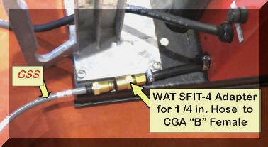 An
adapter
connection method was developed for an automotive manufacturer who uses some wire feeders from Japan. These wire feeders do not use the CGA
032 "B" connector. All flowmeters at their gas supply pipeline were produced in the
USA and use the CGA 032 "B" connector. Also the fabricator wanted
the ability to change wire feeders quickly, interchangeably with US made
feeders. We developed a connector which
solved the problem. They cut the existing shielding gas delivery hose
close to the feeder and installed our WAT-SFIT-4 connector into their existing
short length 1/4 inch ID hose. An
adapter
connection method was developed for an automotive manufacturer who uses some wire feeders from Japan. These wire feeders do not use the CGA
032 "B" connector. All flowmeters at their gas supply pipeline were produced in the
USA and use the CGA 032 "B" connector. Also the fabricator wanted
the ability to change wire feeders quickly, interchangeably with US made
feeders. We developed a connector which
solved the problem. They cut the existing shielding gas delivery hose
close to the feeder and installed our WAT-SFIT-4 connector into their existing
short length 1/4 inch ID hose.
|
 This
adapter fitting has a hose barb on one end and a
female CGA 032 "B" connector on the other. They used standard GSS hose with CGA
"B" connectors
and simply screw the feeder end into the WAT-SFIT-4 on their other US
made wire feeders. The metal to metal
seats on CGA "B" connectors are precision made and less likely to leak. An
adapter is also available for an existing 3/16 inch ID hose, part number
WAT This
adapter fitting has a hose barb on one end and a
female CGA 032 "B" connector on the other. They used standard GSS hose with CGA
"B" connectors
and simply screw the feeder end into the WAT-SFIT-4 on their other US
made wire feeders. The metal to metal
seats on CGA "B" connectors are precision made and less likely to leak. An
adapter is also available for an existing 3/16 inch ID hose, part number
WAT
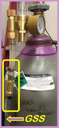
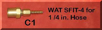 SFIT-3 and a 5/16 inch ID hose, part number SFIT-5. If you
would like to use this approach, a WAT-SFIT-4 is available on
the purchase page and fit either end of
a GSS. SFIT-3 and a 5/16 inch ID hose, part number SFIT-5. If you
would like to use this approach, a WAT-SFIT-4 is available on
the purchase page and fit either end of
a GSS.
An SFIT-5 is shown on the picture right attached to a regulator/flowmeter that came with an EVERLAST Combo Welder/Plasma Cutter. That system requires a large hose ID to flow the high volume of air needed when plasma cutting. However it also wastes a great deal of gas and creates a high gas surge at the weld start resulting in inferior start quality. Installing a GSS using an SFIT-5 solved both the gas waste and weld start problem!
Click to
Email Us if You Need the WAT-SFIT-3 or WAT-SFIT-5
 We can supply either end of a GSS hose with other fittings such as a 1/4 inch female NPT (shown on left) or a female CGA "B" fitting. These may be useful for Robot welder installations. We can supply either end of a GSS hose with other fittings such as a 1/4 inch female NPT (shown on left) or a female CGA "B" fitting. These may be useful for Robot welder installations.
These could also be used with simple Tee fittings to simply mix two gases. 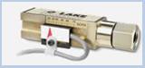
Special fittings may also be useful when installing a gas flow monitor (example shown right) in the shielding gas delivery hose.
Click to to
Email Us with a Specific Fitting Need |
Have a Dual Wire Feeder
 with
Two Gas Inlets? with
Two Gas Inlets?
Do you use the same shielding gas for both sides? We
have a special arrangement for this situation. It is two short GSS's
connected to a brass TEE fitting that has a female CGA Inert Gas 032 "B" fitting
inlet. It is Part # WAT-DFT. It comes
standard with 1 foot long GSS's
with end fittings that include peak flow orifices.
 You
will need to add a GSS to the
inlet of the length to go from the TEE fitting to the gas control device at
the pipeline or cylinder. Order the required length.
We will equip the system with the proper "B" fittings. You
will need to add a GSS to the
inlet of the length to go from the TEE fitting to the gas control device at
the pipeline or cylinder. Order the required length.
We will equip the system with the proper "B" fittings.
From time to time we are
asked, if an FB3 can be connected to an existing
gas delivery hose and have the GSS
benefits. The answer is NO! The gas savings comes
primarily from the reduced gas volume in the GSS
hose compared to a standard 1/4 inch ID hose. The GSS needs to be full
length.
Need longer than 25 feet? No problem, we have customers using 100 foot GSS's. CLICK the "Contact Us for a Quote" below and provide details of your pipeline pressure and desired flow rate range.
If you
need this approach,
Contact Us for a Quote. |
Using
a Gas Mixer?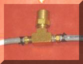
We have supplied a
number of customers with GSS's
that are using gas
 mixers .
Depending on the type of mixer used, such as simple TEE mixers, to achieve the gas saving and performance benefits,
it may be necessary to use
GSS hose from gas supplies to the mixer and from the mixer
to the TIG or MIG welder. More expensive mixing devices may only need the
GSS from the mixer output to the welder or wire feeder.
Email with the details of what mixer is being used and the lengths of the hoses
employed and we'll quote what to
purchase. mixers .
Depending on the type of mixer used, such as simple TEE mixers, to achieve the gas saving and performance benefits,
it may be necessary to use
GSS hose from gas supplies to the mixer and from the mixer
to the TIG or MIG welder. More expensive mixing devices may only need the
GSS from the mixer output to the welder or wire feeder.
Email with the details of what mixer is being used and the lengths of the hoses
employed and we'll quote what to
purchase. |
Regulator/Flowgauges, (photo below left),
like the one on Jason Insley's welder and the one supplied with the Miller 211 welder operate by setting gas pressure ahead of a
very small orifice. They are calibrated in cubic feet per hour (CFH)
NOT psi. They use a principle called
"Choked Flow"
which limits the velocity of gas through the small orifice to the speed of
sound at
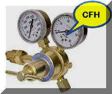 the
pressure setting. Depending on the orifice size, pressures
typically vary from 40 to 60 psi. That small orifice may be in the
outlet fitting, like the one on Jason's welder, or could be inside the
regulator body. When gas is flowing, the gas pressure drops across the
orifice to typically 3 to 6 psi in the gas delivery hose. When welding
stops, gas continues to flow through the orifice and quickly fills the hose
with 4 or 5 times the amount of gas volume until the pressure equals the regulator pressure
setting. That stored excess gas is what causes the "Blast of Gas"
at each weld start or when you are just inching the wire to cut off the end
or positioning it in the weld joint. This not only wastes gas but pulls
air into the gas stream creating excess spatter and possibly internal weld
porosity. the
pressure setting. Depending on the orifice size, pressures
typically vary from 40 to 60 psi. That small orifice may be in the
outlet fitting, like the one on Jason's welder, or could be inside the
regulator body. When gas is flowing, the gas pressure drops across the
orifice to typically 3 to 6 psi in the gas delivery hose. When welding
stops, gas continues to flow through the orifice and quickly fills the hose
with 4 or 5 times the amount of gas volume until the pressure equals the regulator pressure
setting. That stored excess gas is what causes the "Blast of Gas"
at each weld start or when you are just inching the wire to cut off the end
or positioning it in the weld joint. This not only wastes gas but pulls
air into the gas stream creating excess spatter and possibly internal weld
porosity. |
Using
a TIG Torch with a Foot or Hand Off-On Gas Control? Our GSS Has Some Unique Benefits.
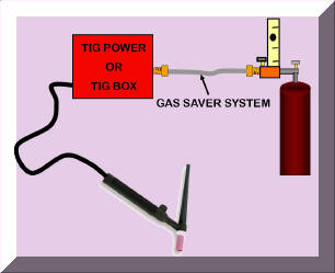 Our Gas Saver System
(GSS)
can improve TIG weld starts and save money. There are a number of companies employing hundreds of GSS's to reduce moisture created porosity when welding aluminum - details below. Our Gas Saver System
(GSS)
can improve TIG weld starts and save money. There are a number of companies employing hundreds of GSS's to reduce moisture created porosity when welding aluminum - details below.
The initial gas flow surge
at a TIG start, in addition to wasting gas, can cause the arc to move unpredictably. This movement is especially a problem at low starting currents. The
turbulent shield created by the gas surge pulls air into
the shielding gas stream causing contamination not just of the weld but also the tungsten electrode. This shortens tungsten life and requiring more frequent dressing. Our
GSS
reduces the excess "gas blast" at each weld start and limits the peak surge flow rate. It still
quickly supplies a controlled amount of extra gas to purge the TIG cup and weld
start area of moisture laden air. It reduces the needed preflow time often used in attempt
to counter the high initial gas surge. The patented
GSS
will not interfere with your flow settings
and has no moving parts to maintain or adjust. Just install it
between your cylinder
(or pipeline supply) and welder (or TIG box) that contains the gas
control solenoid (See Schematic).
It may be or interest that Boeing has 60 GSS's on TIG welders and report, in addition to gas savings, they reported their preflow time is reduced 4 fold for the critical parts they weld!
REDUCE WELD POROSITY WHEN WELDING ALUMINUM!
The GSS has a unique benefit particularly helpful when welding aluminum that was discovered by a large industrial gas producer that fabricate their own cryogenic liquid gas tanks! They always had weld porosity problems in the humid summer months that were eliminated with the use of GSS's on their TIG welders. They found the GSS significantly reduces moisture permeation in standard gas delivery hoses. CLICK FOR DETAILS
TESTIMONIAL
Here is a comment from Terry,
who owns a FAB shop in California, about the use of our GSS for his
TIG welders:
"Received and tested the GSS and compared it to a "low pressure "Gas Guard" surge reducer on
my TIG welders where we mix helium into the argon stream. Mixing the two
gases is particularly difficult with the low pressure device. Your hoses
eliminate the difficulty and produce the same reduced surge and gas savings
results."
Terry
has purchased GSS's for his TIG and MIG welders.
Note: See these links
providing information about low pressure "surge reducing devices" such as the Gas Guard referred to by Terry, which
create more problems than they solve!
Why "Low Pressure" Surge Reducing Devices
Don't Work!
Also See Video
Have
a Question About Your TIG Set-Up? Email |
| Other Installations Questions, Please Send
Email by Clicking on Subject 1, 2, or 3 Below: |
|
1.
Using a Pipeline Supply and want options for the best way
to control shielding gas flow?
|
|
2.
Are Welders Setting Excess Shielding Gas Flows? |
Our Patented Flow Rate Flow Limiter Can Be the
Answer. CLICK HERE.
|
|
3.
Have
Other Questions About Installation? Please Specify in an Email; Include
your address.
E-mail
Purchase Product

|


