Automatic Flow Compensation
To Understand Why Low Pressure Devices like "Gas Guards" or Similar Devices Create Problems, and Often Frustrate Welders, It's Helpful To Know What The "Smart" Engineers Designed Into "Quality" Flow Control Systems When MIG Welding Was Introduced in the 1950's!
How Does “Automatic Flow Compensation” Work?
Why Is It Needed?
We often receive questions
about “Automatic Flow Compensation.” Since the introduction of
MIG welding in the 1950's, Automatic Flow
Compensation was designed into MIG (and TIG) gas delivery systems. Those engineers were "smart" and understood production MIG (and to some degree TIG) gas flow would vary with the inevitable flow restrictions! They both designed and sold MIG and TIG products! The two major companies designing these systems sold Inert gas and undestood the gas flow dynamics. It maintains the desired
preset flow when spatter builds in the MIG gun nozzle, the gun cable or gas delivery
hoses are bent and twisted, etc. The engineers that designed these systems understood MIG  (and TIG) and the inevitable flow restrictions that occur while welding. (and TIG) and the inevitable flow restrictions that occur while welding.
The following
Q&A provides an explanation of how it works. Note it was not invented for MIG or TIG welding, Galilao in the 1600rds (pic left) would understand how it works since he made measurements of the speed of sound! If he could easily understand the concept so can you!
The principle is the same reason you see lightening before you hear the resulting thunder! The pressure wave that creates sound that gets to your ear can only travel at a maximum speed of 767 mph. The light from the lightening travels 1 million times faster!
|
|
|
|
Question:
With no apparent feedback circuits or moving parts;
how does "Automatic Flow Compensation" work?
Answer:
If a needle valve or fixed orifice is employed
to control the gas flow rate the pressure upstream and downstream of the
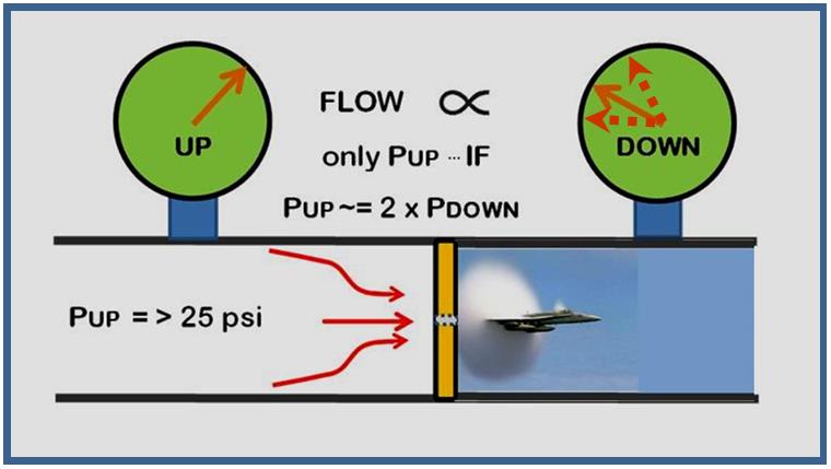
flow control defines the flow rate. A unique phenomena occurs when the pressure
downstream of the needle valve or orifice is less than about 1/2 the
upstream pressure (2.1 times to be exact, but twice provides sufficient
accuracy for our purposes.) This phenomena is called critical flow or
choked flow and the velocity of the gas in the needle valve or orifice cannot exceed the speed of sound! (Above Pic.) Note all pressures are measured as absolute
pressure which is gauge pressure reading plus atmospheric pressure or 14.7
psi (15 psi is sufficient for our purposes.)
For a typical MIG system the pressure needed to flow gas through a feeder
and gun will be
only about 5 psi
or converting to absolute pressure 20 psia (psia is the symbol for absolute pressure.)
Therefore the minimum pressure upstream of the flow control (needle valve or
orifice) needed to achieve critical flow is
twice 20 psia or 40 psia. 40 psia stated as gauge pressure is 40 psia - 15 psi=
25 psi. Then 25 psi is the minimum regulator or pipeline
pressure needed upstream of the flow control orifice or needle valve.
Note: Although referred to
as "Choked Flow" or "Critical Flow" it would be more accurate to call this
phenomenon "Choked Velocity!" That is because the Velocity is
fixed at the speed of sound but as the upstream pressure increases so does the gas
density, therefore the flow volume will increase- - - more on that subject below.
|
|
Question:
Intuitively, both the upstream and downstream pressure
should control flow; why when downstream pressure is less than 2.1 times
upstream pressure does that no longer apply?
Answer: It is correct that until the upstream pressure is 2.1 times the downstream
pressure both pressures determine flow. The flow equations are rather
complex but flow rate can be calculated given both pressures, orifice size
and gas type.
However the gas velocity in the needle valve or fixed orifice cannot
exceed the speed of sound. Therefore, for a given upstream pressure,
once the gas velocity reaches the speed of sound, a further
reduction in downstream pressure has no influence on flow. Using flow
equations the downstream pressure that causes this "choked flow" to
exist occurs when it reaches 1/(2.1) = 0.48 times the upstream pressure
(both measured as absolute pressure, i.e. gauge reading + 14.7 psi at sea
level. )
|
|
Question:
Why is velocity limited to the speed of sound?
Answer:
I recall an explanation
given many years ago by my Fluid Flow Professor that may help explain this
phenomena. When asked why the flow doesn't increase with a continued
reduction in downstream pressure? He said "It might if it knew the
pressure was lower but the pressure wave telling it the pressure is reduced
can only travel at the speed of sound so it never gets there to let it know!"
Not a technical explanation but it helps me remember what is occurring!
The pressure wave causing
sound only travels at a limited speed. That is why you see lightening
before you hear the resulting thunder! The lightening is seen first
since light travels at 300,000,000 m/sec while the sound produced travels at
only 345 m/sec!
|
|
Question:
How does "Automatic Flow Compensation"
control the downstream pressure?
Answer:
When choked flow exists in the orifice of needle valve throat , the
downstream pressure
is controlled automatically by the fact that flow rate is being established in the
needle valve or fixed orifice. The downstream pressure will be whatever it takes to flow the gas coming
through the orifice as long as the downstream pressure is less than about
~1/2
the upstream pressure. The orifice flow is controlled only by the pressure
upstream in that situation. Therefore as restrictions occur in the system,
due to spatter build-up, twisted gun cables etc, the pressure will
automatically raise to delivery that flow (or automatically fall when
spatter is removed or MIG gun cables have less twist.)
|
|
Question:
If the speed of sound in the orifice determines flow, why does flow rate change with a
change in upstream pressure?
Answer:
Even
though the
maximum velocity is the speed of sound, the density of the gas increases
with pressure. Velocity is still the speed of sound but the
volume of gas measured at Standard Pressure and Temperature increases.
|
|
Question:
What happens when the pressure upstream of the orifice is less than 25
psi, as is the case when low pressure devices are employed to reduce gas
surge?
Answer:
Comparative
flow tests were made with a typical system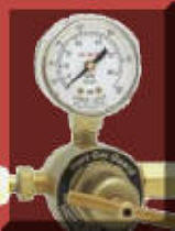
 having
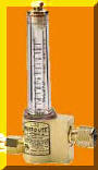
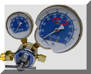
a delivery pressure of 25 psi (Photo Left) and a commercial low pressure
"Gas Guard" device (Photo Right) that required a pressure of only 9 psi to flow the 31 CFH. This particular low pressure system mounts at the wire feeder and
includes a flow reading pressure gauge. having
a delivery pressure of 25 psi (Photo Left) and a commercial low pressure
"Gas Guard" device (Photo Right) that required a pressure of only 9 psi to flow the 31 CFH. This particular low pressure system mounts at the wire feeder and
includes a flow reading pressure gauge.
[ Note: the marketing information about the Gas Guard device tested does not say it uses low pressure to limit surge-but it does! All low pressure devices have similar problems. The company who makes Gas Guards also sells low pressure devices that mount on a pipeline gas supply, as well as regulator/flowgauges and regulator/flowmeters that mount on cylinders. Companies that sell only higher pressure "Compensated" flow control devices are Victor, ESAB/Victor and Miller/Smith. ]
Of interest, when attending the Beijing ESSEN Welding Fair in China, I found all of the flow control manufacturers in China and Japan built systems that operate at ~50 psi (typically 3 bar. ) In discussions with their technical personnel they understood the benefits of "Choked Flow." Scroll down to the bottom of this page to see way all hospitals use 50 psi flowmeters!
In these tests both devices were set at 31 CFH with a restriction in the
feeder/MIG gun system requiring 5 psi to flow that amount of shielding gas.
Restrictions were varied simulating spatter build-up in the gun nozzle,
partially blocked gas diffuser, twisted gun cable
and debris accumulation in the wire conduit which is often doubles as a gas
passage in the MIG gun cable. These restrictions were added and removed for
these tests.
The
restriction pressure drop varied from 3 psi to 8 psi. The flow
settings in
both cases were not changed, as if
flow controls were pad-locked after being set at 31 CFH.
See flow
results in table below:
|
Flow Control System |
<Typical
Production Restriction Range> |
|
3 psi |
4 psi |
5 psi |
6 psi |
7 psi |
8 psi |
|
Conventional = 25 psi; min. pressure for Automatic Flow Comp. |
31 CFH |
31 CFH |
31 CFH |
31 CFH |
31 CFH |
31 CFH |
|
Low Pressure
"Gas Guard"
= only 9 psi |
37 CFH |
34 CFH |
31 CFH |
27 CFH |
23 CFH |
16 CFH |
% Change in Flow with
Gas Guard |
+19% |
+10% |
Preset Level |
-13% |
-26% |
-48% |
Note: Fabrication codes like AWS, ASME and others only allow a maximum variation in an essential variable. Shielding Gas Flow Rate is an Essential Variable and deviations are usually limited to plus or minus 10%. Therefore the use of this low pressure "Gas Guard" device will quickly cause the parameter to fall outside the limit with just a modest flow restriction change! A much lower flow restriction change than we have measured in production operations.
In fact these flow tests were made after a welding engineer was told by an inspector from their earthmoving equipment customer (after the inspector checked flow rates at the MIG gun) that there were outside their own procedure specifications. The welding engineer had just checked flows at the MIG gun the day before and they were centerline! He asked us why this variation existed and didn't show on the included gauge. He was using the "Gas Guard" device tested. We showed him why!
Note
actual flow in our tests was measured with our WAT PFM portable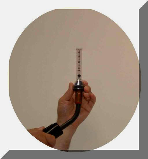 flowmeter at the gun nozzle (see photo
right.) This is an accurate and very repeatable measurement device.
As noted, the flow control
device with upstream pressure of 25 psi held the same preset flow of
31 CFH as the restrictions
were varied from 3 to 8 psi. With the low pressure system, without any
change in flow setting, the flow actually varied from a high of
37 CFH to a low of 16 CFH !
This range is much larger than any acceptable Welding Procedure
Specification would allow. No wonder welders complain when flow drops
below 20 CFH.
flowmeter at the gun nozzle (see photo
right.) This is an accurate and very repeatable measurement device.
As noted, the flow control
device with upstream pressure of 25 psi held the same preset flow of
31 CFH as the restrictions
were varied from 3 to 8 psi. With the low pressure system, without any
change in flow setting, the flow actually varied from a high of
37 CFH to a low of 16 CFH !
This range is much larger than any acceptable Welding Procedure
Specification would allow. No wonder welders complain when flow drops
below 20 CFH.
Of interest, the flow calibrated pressure gauge included
with the low pressure "Gas Guard" device read a constant
31 CFH while the flow varied from 37 CFH to
16 CFH. The gauge is 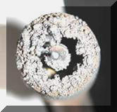 not reading flow but pressure above an orifice - which didn't change! In
this instance we measured the pressure and it was only 9 psi well below the 25 psi needed to
achieve "choked flow." Therefore the actual shielding gas flow
changes when the inevitable flow restrictions occur while welding, such as
spatter build-up in the nozzle and gas diffuse. Worse, the flow gauge gave a false impression that flow was consistent. not reading flow but pressure above an orifice - which didn't change! In
this instance we measured the pressure and it was only 9 psi well below the 25 psi needed to
achieve "choked flow." Therefore the actual shielding gas flow
changes when the inevitable flow restrictions occur while welding, such as
spatter build-up in the nozzle and gas diffuse. Worse, the flow gauge gave a false impression that flow was consistent.
In fact, welders are smart,
and when poor weld results are observed from low flow they increase the gas flow!
The flow calibrated gauge included with this "Gas Guard" device may
say 30 CFH but that is NOT the actual
flow, as observed in our test, it may be only 16 CFH! Welders
logically increase the flow setting. When restrictions are reduced, they
do not turn it back! The "boss" may get mad an install a pad lock on
the device believing the inaccurate flow calibrated pressure gauge! Welder attitude is
blamed for setting excess flows and wasting gas- when they were probably
right in making adjustments! Unfortunately, unless flow is measured at
the MIG gun nozzle, neither welder or management know what the gas flow is!
It certainly is not what the reading on the low pressure "Gas Guard" device reads!
|
|
 Sidebar: Sidebar:
Does that mean my
regulator/flowgauge does not read accurately? NO IT DOES NOT! Most
quality regulator/flowgauges
operate above 25 psi (typically 40 to 60 psi at practical flow rates) and
in the "Choked Flow Range." Preset flow is "Automatically Compensated"
and the gauge reads accurately. Note, the red circle in the picture
shows output gauge is calibrated in CFH NOT psi. |
|
Some low pressure ad-on
devices use even lower pressures and can create even larger flow variations.
The one shown in 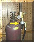 the photo right (yellow arrow) attaches to a standard
flowmeter and sets flow by setting pressure. Where the low pressure
device test mentioned used above changed 4 CFH with a 1 psi increase in flow
resistance; in tests of this device the equivalent of a 1 psi increase in
resistance caused the flow to reduce 8 CFH! the photo right (yellow arrow) attaches to a standard
flowmeter and sets flow by setting pressure. Where the low pressure
device test mentioned used above changed 4 CFH with a 1 psi increase in flow
resistance; in tests of this device the equivalent of a 1 psi increase in
resistance caused the flow to reduce 8 CFH!
Unfortunately some fabricators who have tried and rejected these
low pressure surge redacting devices are
fearful our Gas Saver System (GSS))
may cause similar problems or welder rejection. Our patented
GSS does not alter pressures and will not cause flow
variations! Welders appreciate the starting benefits!
See Overview of
GSS
BE CAREFUL SOME OF THESE
DEVICES DO NOT MENTION THAT THEY EMPLOY LOWER PRESSURE!! THEY MAY SAY
THEY STOP OR "GUARD" AGAINST SURGE.
ALSO ANY DEVICE THAT
MOUNTS DIRECTLY AT THE FEEDER WILL NOT PROVIDE SUFFICIENT EXTRA START GAS. That includes simple orifices, flowmeters or regulators that set gas flow rates.
EMAIL IF YOU HAVE A QUESTION ABOUT A SPECIFIC MODEL.
|
|
Question:
Are there production examples where low pressure devices have
caused problems?
Answer:
We have encountered a number of
examples where problems have
been observed with low pressure devices and they were removed and discarded.
The following are four specific reported problems:
First Case:
A
Welding Engineer at a large automotive parts supplier installed low pressure
devices that mounted at the feeder and included a pressure calibrated flow
gauge (the same "Gas Guard" device used in the tests mentioned above.) Here are
his quotes
about the  experience: experience:
“After purchasing and using 32 low pressure gas saving
devices (the same product used in our tests mentioned above) that mounted at the wire feeders we decided to
discard all of them! There were two major problems:
1) Lack of sufficient extra gas at the start made inferior starts and
2) Large flow variations from preset levels were evident when flow was
checked at the MIG gun. In fact as he stated; "Even if the flow was blocked,
the flow calibrated pressure gauge supplied with these devices had the same
preset reading!"
Second Case.
A
Welding Engineer at a major Midwest heavy construction equipment
manufacturer
was observing porosity in the same weldment in one plant and not in another.
He performed a very careful, systematic analysis of the problem.
A fishbone troubleshooting diagram was developed with over 30 items
considered in attempt to solving the problem. It appeared to be a nitrogen
porosity problem so he looked at all the possible causes. He checked for
pipeline, solenoid, feeder plumbing leaks, tested a cylinder gas supply to validate the quality of
shielding gas and many others items. He even tried a different type and
manufacturer of the solid wire they were using. the same weldment in one plant and not in another.
He performed a very careful, systematic analysis of the problem.
A fishbone troubleshooting diagram was developed with over 30 items
considered in attempt to solving the problem. It appeared to be a nitrogen
porosity problem so he looked at all the possible causes. He checked for
pipeline, solenoid, feeder plumbing leaks, tested a cylinder gas supply to validate the quality of
shielding gas and many others items. He even tried a different type and
manufacturer of the solid wire they were using.
After all this testing and
elimination of differences he found one major cause was the plant with the
porosity problem was using low pressure surge reducing devices on their
welders! The same "Gas Guard" device shown in the comparison test mentioned above. These were removed and the
problems went away! Variability in flow was probably allowing
nitrogen to enter the shielding gas stream. If shielding gas flow rate
is too high or too low this can occur.
We find fabricators often
use excessive flow rates. Flow settings above approximately 50 CFH with a typical 5/8 inch ID
gun
nozzle are just pulling air with it's 70% nitrogen and moisture into the
weld due to turbulence in the shielding stream.
Third Case:
When evaluating the fittings needed for adding
GSS's to 45 MIG welders at a bar joist manufacturer, it was observed
that one installation had
a low pressure regulator/flow control device mounted at the feeder (the same
"Gas Guard" device
used in case 1 and case 2). It had an output pressure gauge calibrated in CFH. The maintenance manager indicated these had been installed on all welders
several years before at a
cost much higher than the
GSS and had to be removed due to inconsistent results! The one
remaining was adjusted at a very high flow rate according to the flow gauge
reading. The maintenance manager indicated it would not be reinstalled and
was surprised it was still there! installation had
a low pressure regulator/flow control device mounted at the feeder (the same
"Gas Guard" device
used in case 1 and case 2). It had an output pressure gauge calibrated in CFH. The maintenance manager indicated these had been installed on all welders
several years before at a
cost much higher than the
GSS and had to be removed due to inconsistent results! The one
remaining was adjusted at a very high flow rate according to the flow gauge
reading. The maintenance manager indicated it would not be reinstalled and
was surprised it was still there!
Fourth Case:
A fabricator making Catalytic Converters had 70 new MIG Robots installed.
The systems integrator used a "Gas Guard" low  pressure device mounted at
the pipeline drop (this is a model of the device used in the above cases
that mounts at the pipeline.) Experiencing flow variations and seeing
the information on our web site they were removed and replaced with
conventional flowmeters. They used flowmeters designed to read accurately at 50 psi
so flows could properly read flow directly, without the need for a
conversion. Flow inconsistences were eliminated and measurements made at the MIG gun nozzle measured the same as the flowmeter
reading even when spatter and other restrictions occurred in production. pressure device mounted at
the pipeline drop (this is a model of the device used in the above cases
that mounts at the pipeline.) Experiencing flow variations and seeing
the information on our web site they were removed and replaced with
conventional flowmeters. They used flowmeters designed to read accurately at 50 psi
so flows could properly read flow directly, without the need for a
conversion. Flow inconsistences were eliminated and measurements made at the MIG gun nozzle measured the same as the flowmeter
reading even when spatter and other restrictions occurred in production.
Bottom
Line:
Low pressure at first
appears to offer a solution to MIG weld start gas surge, as do flow restriction orifices mounted
at the feeder. But both approaches create other larger, but less obvious problems!
You'll note
the comments
about lack of sufficient extra gas making inferior starts in one of the
reported problem cases. That will
occur with any device that controls gas flow at the feeder, low pressure
devices, flowmeters or simple orifices. We have seen a number of
problems caused by the use of this flow control location.
A
recent survey of a shop with 100 MIG welders having flowmeters mounted at
the feeder showed all set with excess flow. The shop uses 0.045
diameter solid wire. No flowmeter was set below 50 CFH, about 25% were
set at the highest reading on the flowmeter (65 to 70 CFH) and approximately
25% had the flow indicator ball pinned to the top of the flow tube!
Our tests show shielding gas flow can be as high as 125 to 150 CFH when the
flowmeter needle valve is fully opened.
THE
WELDERS WERE NO DOUBT TRYING TO COMPENSATE FOR THE LACK OF SUFFICIENT EXTRA
GAS NEEDED TO PURGE THE WELD START AREA.
|
SIDE BAR: All Hospital Regulator/Flowmeters Operate at 50 psi!
The flow rates used to supply oxygen to a hospital patient are similar to MIG flow rates, about 0.5 CFM or 30 CFH. To insure that possible restrictions, from kinks or bends DO NOT interfere with the Doctors prescribed flow settings
they use a "Choked Flow" design, just like in MIG/TIG welding!
 Assuming they only need a low 3 psi pressure at the tight fitting mask, how much pressure drop can they have and still deliver the flow setting? Doing the math; 3 psi + 15 psi = 18 psia (absolute pressure.) Then twice that pressure is needed before the needle valve or 36 psia. To get back to gauge pressure subtract 15 psi and only 21 psi is needed. By using a 50 psi regulator there can be a 50 psi - 21 psi = 29 psi drop. Therefore even with pinched hose restrictions causing up to a 29 psi pressure drop, the prescribed preset flow will be maintained! Assuming they only need a low 3 psi pressure at the tight fitting mask, how much pressure drop can they have and still deliver the flow setting? Doing the math; 3 psi + 15 psi = 18 psia (absolute pressure.) Then twice that pressure is needed before the needle valve or 36 psia. To get back to gauge pressure subtract 15 psi and only 21 psi is needed. By using a 50 psi regulator there can be a 50 psi - 21 psi = 29 psi drop. Therefore even with pinched hose restrictions causing up to a 29 psi pressure drop, the prescribed preset flow will be maintained!
|
| A
Technical Article About "Automatic Flow Compensation" Was Published in The
American Welding Societies Technical Journal. CLICK Link Below. |
See
Technical Article discussing Automatic Flow
Compensation Published in AWS Journal April 2007 (Note you'll download that issue, GO TO pp 22) |
| See
Other Questions and Answers; Click Link Below: |
|
Q&A About Extra Gas Needed at Weld
Start |
|
Q&A About Ideal Gas Delivery Systems |
|


