|
What is the Ideal
Shielding Gas Delivery System?
A question we're often
asked. Here are some answers: |
|
Just Replace Your Gas Delivery Hose With Our
GSS |
|
The IDEAL GAS
DELIVER SYSTEM Should:
-
Operate at
Greater than 25 psi for
"Automatic Flow Compensation" Retaining Preset Gas Flow as
Flow Restrictions Occur While Welding
-
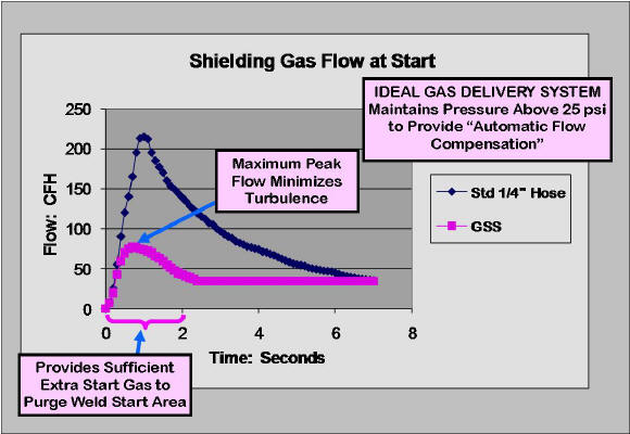
Provide a
Controlled Amount of Extra Start Gas to Quickly Purge Air From the Weld Start Area
Improving Weld Start Quality
-
Limit
Starting Gas Peak Flow Rate Avoiding Turbulence That Causes Air to Be
Mixed
Into the Shielding Stream
-
Eliminate
Excess Stored Gas by When Welding Stops. Significantly Reducing
Gas Waste at each weld start . Cutting Total Gas Use by ~50%
The patented
GSS does all of these things at a low
cost!
SEE Why Low Pressure "Gas Guards" and Simple
Orifices Mounted at the Wire Feeder Don't Work
Does Your Pipeline Pressure Vary?
See Possible Solution. |
|
Question:
What is the best way to deliver shielding gas to
a MIG system?
Answer:
The
system
should quickly provide extra gas at the weld start purging air from the weld start area at a maximum flow rate
that avoids
excess turbulence . It must also automatically maintain preset gas
flow when restrictions occur such as spatter buildup. Our patented Gas Saver System (GSS
TM)
does all these things and more - it eliminates the excess "gas blast"
and gas waste at each weld
start and can cut total gas use in half while improving weld start quality. It
does this with no moving parts or needed maintenance!
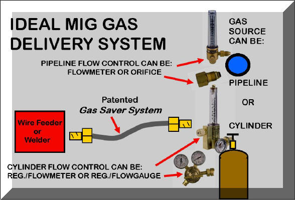
For systems with up to 50
feet from gas cylinder to wire feeder or where a hose connects
from a pipeline to the feeder; the best systems are shown in the above
schematic. It
consists of a rotameter flowmeter and our Gas Saver
System (GSS.) This system will
work for any gas supply.
The benefits of
this system include:
-
The gas flow can be quickly seen
and read by the position of the flow indicator ball to define if your within
your Weld Procedure Specifications. Note for cylinder gas supply, a
regulator/flowgauge also provides these benefits, see details below.
-
The GSS eliminates
the excess "gas blast" and gas waste at each
MIG weld start .
-
This arrangement quickly delivers a
sufficient amount of extra shielding at the weld start to purge the weld
start area, MIG gun nozzle and gun gas hose, resulting in higher quality
weld starts with less spatter and internal weld porosity. It delivers
this extra gas at a controlled peak surge flow rate that minimizes
turbulence. CLICK to see details of why extra gas at weld start is needed)
-
The GSS also
maintains the system pressure so automatic flow compensation is maintained.
This feature maintains flow even when spatter builds in the gun nozzle or
when gun cables are twisted etc. "Automatic flow compensation" has
been built into gas delivery systems
since the introduction of MIG welding in the 1950's!
(CLICK for more information on that
feature.)
|
|
Question:
What if we have over 50 feet from gas supply to wire feeder?
Answer:
The GSS can operate up to
100 foot from gas supply to wire feeder if
cylinder regulator pressure or pipeline pressure is 50 psi or higher.
Email and define the regulator/flowmeter model for cylinder supply and the pipeline pressure if on pipeline gas supply.
TechSupport@NetWelding.com
|
|
 Question:
Suppose we
want to lock the flow setting to stay
within our Welding Procedure Specifications and to avoid shielding gas
waste? Question:
Suppose we
want to lock the flow setting to stay
within our Welding Procedure Specifications and to avoid shielding gas
waste?
Answer:
You can use our Flow Rate
Limiter and Lock that fits most flowmeters and regulator/ flowmeters.
You set the flow and lock the control knob so it can not be turned further
to increase flow.
CLICK for Details
|
|
 Question:
We don't like to use rotameter flowmeters since they are
somewhat susceptible to breakage. What can we use? Question:
We don't like to use rotameter flowmeters since they are
somewhat susceptible to breakage. What can we use?
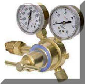
Answer:
A flowgauge/regulator will
work fine for cylinder gas supply (photo right.) We have many customers using
these with our GSS . For typical flow rate settings the regulator is often operating
at 50 to 80 psi. Even though your reading flow in CFH on the gauge your actually
setting the pressure upstream of a critical orifice. The GSS
is very beneficial with these systems since significant excess gas is stored in the delivery
hose every time welding is stopped. The amount of stored gas as measured at standard
pressure (what you pay for) can exceed 6 times the physical hose volume!
SEE WHY
|
|
Question:
We
don't like to use rotameter flowmeters and we are pipeline gas
supply. What can we use?
Answer:
Some fabricators use a flow control orifice mounted at the pipeline
drop after the required shut-off. The orifice size is
selected to provide the desired flow. Since it can't be adjusted the
flow is set to the highest level that will be needed. Also whe welding stopps gas continues to flow through the orifce and fills the gas delivery hose with high pipeline pressure. When welding starts that produces a high gas surge, wasting gas and creating inferior weld start quality.
We offer a
unique, patented Orifice controled Gas Saver System OGSS that solves the surge and gas waste probem. CLICK This Link For Info!
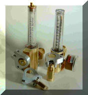
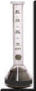 When
using an orifice to control flow, it is advisable to measure gas flow at the
MIG gun nozzle with a portable flowmeter like the one shown on the left.
CLICK on picture to see details of this device which we offer for sale.
It is an inexpensive way to check for actual flow out of the gun nozzle. When
using an orifice to control flow, it is advisable to measure gas flow at the
MIG gun nozzle with a portable flowmeter like the one shown on the left.
CLICK on picture to see details of this device which we offer for sale.
It is an inexpensive way to check for actual flow out of the gun nozzle.
With this system the
GSS is very important since pipeline
pressures are usually 50 psi or higher and weld start gas surge is very high.
This high gas surge causes turbulent flow resulting in inferior start
quality as well as significant gas waste.
|
|
Question:
Is
it sufficient to just use the
GSS to replace the shielding gas delivery hose
(from the gas supply flow control to wherever the gas control solenoid is located?) What about the gas delivery lines and torch lines after the
solenoid?
Answer:
The excess gas stored when welding stops (which
is mostly wasted when welding starts) causes the high flow surge at the weld start.
This excess only
exists between the gas supply flow control and the gas control
solenoid. The gas lines after the solenoid and those in the torch are
not exposed to the high pressure when welding stops. In fact depending on how
long the weld is stopped, air will diffuse back into these lines.
SEE Why Some Extra Gas is Needed at
the Weld Start.
|
|
Question:
We
have only 6 foot gas delivery hoses, is there a benefit to using a GSS
?
Answer:
Yes, there is. A
company with 128 welding robots recently asked the same question. They
were running a Black Belt Lean Manufacturing study. After purchasing
four 6 foot GSS systems (WAT FB6)
they ran extensive tests on their various parts. They found a minimum
of 25% and with some parts over 40% gas savings! Their parts are very
repetitive so the comparison gas usage test data is very reliable
See Details. The
Bottom Line is they purchased 128 systems!
|
|
Question:
We
have very long gas lines, is there anything we can do?
Answer:
Yes, we have developed
and patented systems for any length gas delivery hose, even those used in shipyards with
gas delivery lines exceeding 200 to 300 feet. Our patented Orifice controled Gas Saver System OGSS solves the surge and gas waste probem. CLICK This Link For Info!
|
|
Question:
Our pipeline supply pressure varies a great
deal as welding machines come on line , is there anything we can do?
Answer:
Yes, the same patented systems developed for very long gas delivery
hose lines can be effective where pipeline pressures vary. Please
supply details of your pressure ranges observed, number of welders and
desired flow rates. Email to:
TechSupport@NetWelding.com
|
|
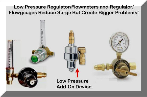
The low pressure devices shown in the above photo, reduce
surge at the weld start but operate well under 25 psi to accomplish the reduction.
This low pressure eliminates
"Automatic Flow Compensation."
Flow varies significantly when spatter builds in the gun nozzle, gas
diffuser and the small gas passage in gun cable partially clogs with wire debris.
CAUTION some brands do not mention
they use" low pressure" they just say the "Reduce Surge" or "Gas Guard"
etc. Some are honest and mention they are "Non-Compensating."
The "Gas Guard" shown at the right of the
above photo mounts at the
wire feeder and in addition to eliminating the very important
"Automatic Flow Compensation" it
also DOES NOT provide sufficient extra gas at the start to properly purge the weld
area and gun nozzle of air- a double "BAD!" The use of these products often frustrates
welders (and management who may wrongly blame the welder for wanting excess
gas!)
Unfortunately after trying these devices and finding the
problems, some fabricators are reluctant to try our patented
GSS not understanding our system has
none of these faults and welders appreciate the weld start improvement
benefits.
See Four Fabricators Who Reported Discarding These Low Pressure
"Surge Reducing" Devices.
 Another
Approach Tried to Reduce Surge, Simple Orifices Mounted at the Wire Feeder,
Rightly Frustrate Welders! At Best, Steady State Flows are Set
Higher Than Needed in Attempt to Correct the Real Problem-Lack of Sufficient
Start Gas! SEE DETAILS Another
Approach Tried to Reduce Surge, Simple Orifices Mounted at the Wire Feeder,
Rightly Frustrate Welders! At Best, Steady State Flows are Set
Higher Than Needed in Attempt to Correct the Real Problem-Lack of Sufficient
Start Gas! SEE DETAILS |
|
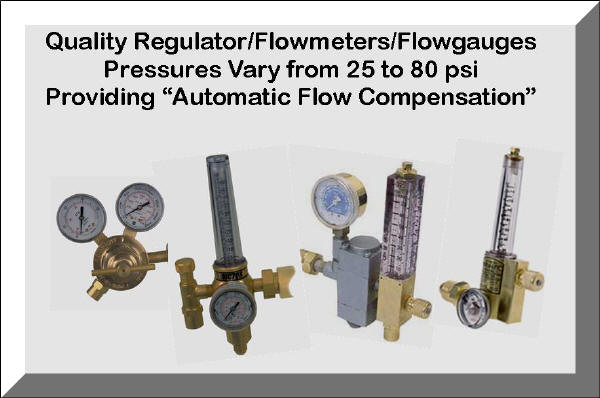
Quality Regulator/Flowmeters and Regulator/Flowgauges
Operate at Pressures Above 25 psi to Automatically Compensate for
Restrictions and Maintain Preset Flow. For CO2 this
pressure can be as high as
80 psi to avoid ice partial formation in the needle valve or orifice.
Click to See How This
Works.
|
|
Does Your Pipeline Pressure Vary?
We
have helped a company who used small copper tubing and when their gas usage
expanded they used pipeline pressures of 125 psi. They had pressure
drops in parts of the pipeline and their flows, as measured on a 50 psi
calibrated flowmeter were far more that the flow reading! The
solution? Add the proper regulator, NOT the cylinder
regulator/flowmeters we had seen employed on pipelines to try to solve the
problem. They do not work!
See
The Following Details. |
| See Other Questions and
Answers; Click Link Below: |
|
Q&A About Automatic Flow Compensation |
|
Q&A About Extra Gas Needed at Weld
Start |

Click Picture Left to
See Video:
What is the Ideal MIG Gas Flow Setting? |


