| Production
Results:

Download
PDF of Several
GSS Testimonials
Click Following Links To Go To Applications of
GSS:
-
Case 1 - -
Truck Body Builder Gets 50% Gas Savings
-
Case 2 - - Improvement in Start Quality with 33%+ Gas Savings
-
Case 3 - - Small and Home Shops Can Also Benefit from GSS
- Case 4 - - 112
GSS's Installed - Saved Over 30%
-
Case 5 - - Aluminum Fabricator Saves 40%; Installs 93
System
- Case
6 - - Bar Joist Mfg. Improves Starts/Saves Gas
- Case 7 - - Truck Storage Box Mfg. Achieves 63% Gas Savings
- Case 8 - - Pipe Fabricator Saves 41% in Shielding Gas
- Case 9 - - Major Trailer
Manufacturer Saves 25% in Production
- Case 10
- 6 Foot Delivery Hose Yields 40+ % Gas Savings
- Case 11 - 350 Gas Saver
Systems Purchased by Military Sub Supplier
- Case 12 - Texas
Hydraulics Saves 35% with Flow Rate Limiters
- Case 13 - Fabricator in
Mexico Saves 30 to 42% Shielding Gas
- Case 14 - Irrigation
Pipe Mfg. Saves 40%, Installs 120 Systems
- Case 15 - Bucyrus China Orders Gas Saver Systems
- Case 16 - Waste Disposal
Mfg Saves 44%, Installs 270 GSS Systems
|
|
Production Example Case 1
Truck Body Builder Gets 50% Savings
With
GSS
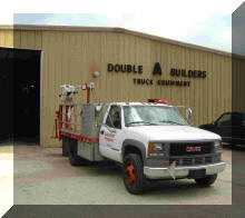 Double
A Body Builders in Pamplico, SC started producing custom truck bodies 40 years
ago. They now consume about 40,000 lbs of steel per week. Most of
the steel arrives flat and is cut, bent and welded into about 120 truck bodies
each month. Double
A Body Builders in Pamplico, SC started producing custom truck bodies 40 years
ago. They now consume about 40,000 lbs of steel per week. Most of
the steel arrives flat and is cut, bent and welded into about 120 truck bodies
each month.
MIG welding
is employed almost exclusively for fabrication. They use 0.035 inch
diameter solid wire which allows welding in all positions. All 23 MIG
welding machines use an Argon/CO2
shielding gas mixture to keep spatter to a minimum and produce high
quality, visually attractive welds. The shielding gas is piped throughout
much of the shop. Most of the wire feeders are located 30 to 40 feet from
the gas supply pipeline.
One off the owners, Ken Ard knew they
were using more shielding gas then needed. Ken heard about the
benefits of a recently invented product developed to solve the waste
problem. He set up a test on two welding machines that had their shielding gas supplied with cylinders. The test started with
full gas cylinders on both welders. One welder incorporated the
GSS and the other used the standard ¼
inch diameter shielding gas delivery hose.
Ken had read about the benefits of the
GSS system and was pleased but not surprised
that
he achieved about twice the amount of welds with the
cylinder of gas on the system with the
GSS
installed.
Shielding gas is a significant cost in the operation and the savings
achieved will assist in keeping Double A Body Builders competitive.
After a year in production Ken Ard is very pleased with the cost savings
results. He has expanded with 20 more welders, each with
GSS.
had their shielding gas supplied with cylinders. The test started with
full gas cylinders on both welders. One welder incorporated the
GSS and the other used the standard ¼
inch diameter shielding gas delivery hose.
Ken had read about the benefits of the
GSS system and was pleased but not surprised
that
he achieved about twice the amount of welds with the
cylinder of gas on the system with the
GSS
installed.
Shielding gas is a significant cost in the operation and the savings
achieved will assist in keeping Double A Body Builders competitive.
After a year in production Ken Ard is very pleased with the cost savings
results. He has expanded with 20 more welders, each with
GSS.
 Go
To published Article Entitled: " A Solution for Welding Shielding Gas Waste." Go
To published Article Entitled: " A Solution for Welding Shielding Gas Waste."
It includes more details of Double A Body
Builders test.
|
| PS:
We have had a number of
trailer/truck body manufacturers purchase systems. After testing 3 systems
one called to purchase 15 more indicating 85% more welds made with the Gas Saver
System. They essentially duplicated the Double A Body Builders test
results and reported getting better starts. Interesting, this company located in Utah purchased an additional
8 to 10 systems at a time and the gas savings achieved paid for the next order!
They purchased a total of 38 x 25 foot
GSS's
(WAT FB25.) |
|
Production Example Case 2
Weld Start Quality Improved Significantly with Gas Saver System While
Gas Consumption Decreased by 33 to 50%
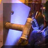
A shop making large diameter pipe evaluated our Gas Saver System (GSSTM)
in their MIG repair rack. In several tests using cylinder gas supply they
found gas savings ranging from a minimum of 33% to over 50%. This was far
more than enough to justify the purchase. However the biggest cost savings
came from improved weld start quality!
Details of Quality Improvement:
While testing the GSS the quality benefits were clearly
observed by the welder. This shop is often required to ultrasonically test all welds.
Weld repair is made with MIG. These repairs must pass ultrasonic tests. For a repair weld,
starts are a significant part of the deposit. With the standard gas delivery
system, flow peak surge at the start exceeded 220 CFH. With the
GSS
the peak was lowered to under 90 CFH and that for a very short time. The welder who was testing the
system knew this excessive surge flow with his standard system caused starting problems
with internal porosity and stated that
he; “cuts the wire back to the tip and starts with the gun above the work to allow the
initial surge flow in attempt to reduce flow rate before the arc strikes!” The pipe
does not leave his work area until all welds are checked and pass UT. He often was holding up production.
Note: After about a year in production the welder
using the GSS
system reported, with no special starting technique, he found almost no weld start porosity compared to numerous problems previously encountered!
Details of Test:
The following shows graphically the peak surge flow measured with their standard
1/4 inch ID gas delivery hose versus our patented
GSS.
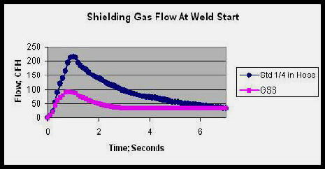
Note the
GSS limits the peak surge and quickly returns
flow to an acceptable level preventing air from being pulled into the shielding gas
stream. With their standard 1/4 inch ID hose the flow exceeds 100 CFH for
about 3 seconds. That flow rate is over the acceptable level needed to
maintain quality Laminar flow and will pull air into the gas stream. You
could use preflow to help, but a 3 second preflow not only wastes gas but would
create a very unhappy welder! Would you like waiting 3 seconds
every time you pulled the trigger? We find welders will zero out preflow
even when it is set at 1/2 second! Weld starts with the
GSS
were smooth with less spatter.
Also important, with the
GSS there is still sufficient extra gas delivered quickly at the weld start to
purge the weld start area and the torch nozzle of moisture laden air.
That extra gas is
essential to avoid a similar problems created by having excess flow rate; Click
to See Why.
MAJOR
QUALITY IMPROVEMENT: As important as the shielding gas savings, with
the 5/8 inch diameter welding torch nozzle employed, excess turbulent flow
exists at about 55 to 60 CFH. Turbulence causes air to be pulled into the arc. Air is 73% Nitrogen
and even 2% Nitrogen in the gas shield can cause porosity in the deposit.
With their standard system when welding started, air was being pulled into the
shielding gas stream for several seconds reducing weld start quality. Devices that
eliminate all extra start gas (those installed directly at the feeder) cause
similar problems as the excess gas flow surge. Moisture laden air is
present in the gas shield at the weld start. See
Results of Start Improvement With
GSS
At Fabricator Where Extra Gas Was Not Present.
|
|
Production Example
Case 3a
Results of
the
GSS
Installed in a Small Shop
Even a 250 amp welder can benefit from the use
of the
GSS.
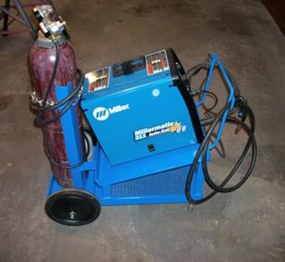
This example is a 250 amp Miller welder with built in feeder. This Street
Rod Builder welds car
frames and accessories. Although the welder and gas cylinder are on a portable cart,
the system was connected with a
conventional 12 ½ foot shielding
gas delivery hose.
This was installed to allow a remote cylinder to be connected when needed such
as when switching to pure Argon for welding aluminum. A regulator/flowgauge is used to set gas flow rates. A pressure
check at the regulator end of the of the gas delivery hose when not
welding showed 30 psi.
The gas flow at weld start
was measured with a specially constructed high capacity rotameter flow meter
mounted over the torch nozzle.
With the original ¼ inch gas delivery hose a gas flow surge of 150 CFH was
measured at the weld start. With the small torch gas cup employed a flow
rate greater than about 40 CFH creates turbulence. Air is then entrained into
the gas stream causing poor weld starts and possibly porosity. This
turbulent flow will take a short time to stabilize to a smooth laminar flow even after
it reaches the
desired preset level.
The
GSS
was easily installed by simply replacing the existing hose and threading on the
GSS
hose fittings (see photo above
right).
Flow surge at the weld start was about 50 CFH with the
GSS
installed and lasted less than a second. With the many short welds made and
frequent inching of the wire at this facility, gas waste and
use will be easily reduced by 50 to 75%. Kyle Bond, President,
indicated a big benefit is the reduced time and effort in changing cylinders less frequently. Since short welds and tacks are the primary use of this welder, the
improvement achieved in weld start quality is also a significant advantage.
Kyle, an excellent automotive painter, was well aware of the effects of
gas surge caused by pressure buildup in the delivery hose when stopped. He
has to deal with the visible effects when he uses the long air hose lines on the
spray gun in his paint booth! It's too bad we can't see the shielding gas
waste as Kyle can the effects of excess pressure when he starts his spray gun!
In fact the amount of excess stored pressure in the paint gun situation is
actually far less than in our welding system! However the paint surge is
visible!
PS:
A customer who purchased a 6 foot
GSS (part number WAT FB6) reports better quality starts and improvement in
"Tank Life," as they phrased their positive comments.
|
Case 3b: Results of the GSS in Home Shop
Beau Straley Improves Weld Quality and Saves Over 60% of shielding gas. He purchased a 4 foot long Gas Saver System (GSS) and reported these gas results:
 "I received the GSS in the early part of a large project, building a 12’ x 24’ steel building. Before installing it on my Miller 211C, I had completed about 30% of the total welds, and had consumed approximately 400 psi of my Argon/25% CO2 gas mixture. As my project progressed I could tell I was consuming much less gas, so I increased the flow rate and my weld quality improved. In the following three months I finished all the remaining welds. The remaining 70% of the welds required only an additional 300 psi consumption of gas. Improvement in my welding technique accounts for part of the gas savings, however, considering I more then doubled the number of welds, while reducing my gas consumption by 25%, I’d say the GSS is a real winner! "I received the GSS in the early part of a large project, building a 12’ x 24’ steel building. Before installing it on my Miller 211C, I had completed about 30% of the total welds, and had consumed approximately 400 psi of my Argon/25% CO2 gas mixture. As my project progressed I could tell I was consuming much less gas, so I increased the flow rate and my weld quality improved. In the following three months I finished all the remaining welds. The remaining 70% of the welds required only an additional 300 psi consumption of gas. Improvement in my welding technique accounts for part of the gas savings, however, considering I more then doubled the number of welds, while reducing my gas consumption by 25%, I’d say the GSS is a real winner!
Before I installed the GSS I was being stingy with the shielding gas flow, and the poor quality of my welds proved that. With the GSS installed I was confident that I was not wasting gas, and increased the gas flow rate. The result withas that the appearance and quality of my welds improved dramatically. It not only saved shielding gas, but it increased my confidence. That’s a winning combination in my book!
Thank you for a wonderful product that actually does what you say it will."
Crunching the math for Beau Straley's gas usage: Over Twice The Welds Made/Used 75% of the Gas or 50%/75% = 67% Less Gas Used with GSS! |
Case 3c: Minnesota Welding School Installs 45 Gas Saver
Systems
and cuts shielding gas use over half
The welding
department at a technical college initially installed 30 Gas S aver
Systemsfrom their liquid gas feed
piped supply to their TIG welders and to gas mixers then MIG welders.
After three months of use this is what the instructor reports: aver
Systemsfrom their liquid gas feed
piped supply to their TIG welders and to gas mixers then MIG welders.
After three months of use this is what the instructor reports:
" We went from using 1 Dewar of Argon (liquid
gas cylinder) a week to the same
size Dewar lasting almost 3 weeks. The companies that sit on
my advisory committee are becoming very interested in this upgrade. I will
keep you posted"
They purchased 15 more Gas Saver
Systems for the 2014 -'15 school year.
Note: An advisory committee member, a Caterpillar Tractor plant, has purchased 100 Gas Saver
Systems! |
|
Production Example Case 4
Automotive
Company Installs
GSS's
on
126 MIG Welders
 An automotive company tested two
MIG welders equipped with cylinders, one with their standard shielding gas
delivery hose the other with a
GSS
. Initial results looked very promising so they installed Gas
Saver Systems on 68 manual MIG welders. They operate with 0.035 inch diameter
solid wire at about 180 amps for most weld joints. The Argon/CO2
gas mixture is delivered to each welder in a very efficient manifold system
using a large diameter pipe header to ensure uniform gas pressure to each of the
flowmeters. The shielding gas
GSS
delivery hose varies in length from 70 to over 100 feet. An automotive company tested two
MIG welders equipped with cylinders, one with their standard shielding gas
delivery hose the other with a
GSS
. Initial results looked very promising so they installed Gas
Saver Systems on 68 manual MIG welders. They operate with 0.035 inch diameter
solid wire at about 180 amps for most weld joints. The Argon/CO2
gas mixture is delivered to each welder in a very efficient manifold system
using a large diameter pipe header to ensure uniform gas pressure to each of the
flowmeters. The shielding gas
GSS
delivery hose varies in length from 70 to over 100 feet.
Initial results in this three shift operation show over a 30% reduction in total
shielding gas used. This will result in a financial savings of over
$50,000/year. Payback will be measured in months. A significant reduction
in excess gas surge at the weld start is also achieved. Weld start quality
improvements are being evaluated. After a year in production 44 more
systems were purchased for installation during a maintenance shutdown making a
total of 112
GSS's
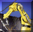
at this location. They then added they then added 14 more for new MIG welding robots.
Note: If you
want to test our
GSS
on a bulk gas supply you can use several cylinders of shielding gas
but must use a regulator for the test that approximates your pipeline pressure.
Email for Details.
|
|
Production Example Case 5
93
GSS
's Installed
at Structural Aluminum Fabricator
Over 40% Gas saving Found
in Their Tests
After measuring
shielding gas surge flow rates in excess of 250 CFH, a primarily structural
aluminum fabricator conducted a test to define the amount of argon/helium
shielding gas they could save using a
GSS.
Tests were conducted in an area where cylinder gas supply is used.
This allowed a direct comparison to be made with their standard gas delivery
hose on one welding system and a
GSS
installed on another. Both were making similar welds. They found over a 40%
shielding gas savings with the
GSS.
Weld start porosity
was also a problem. Air being pulled into the weld zone by the high surge flow rates was no doubt a significant
contributor to that situation. They installed
GSS
on 93 MIG welders both those welding aluminum as well as on those welding
steel. With the high cost of the argon/helium shielding gas mixture the
payback for the
GSS
investment will be obtained in about one month!
Note: If you
want to test our
GSS
for a bulk gas supply you can perform the test with several cylinders of shielding gas
but must use a regulator for the test that approximates your pipeline pressure
when welding stops.
Email for Details.
|
|
Production Example Case 6
Bar Joist Manufacturer Improves Starts and Saves
Gas
 An interesting application of the
GSS validates the need for some extra gas at the weld start. A
bar joist manufacturer was using flow control orifices mounted at the wire
feeders. Argon/CO2 shielding gas is supplied in a pipeline
through about 15 feet of gas delivery hose. The flow control orifice
established the flow at 45 CFH. However the welders wanted higher flow
rates with some even drilling out the orifice! The welding engineer wanted to avoid wasting
shielding gas. With this flow setting arrangement where control is mounted at
the feeder next to the gas solenoid there is insufficient extra gas provided at the weld start.
This lack of extra gas prevents to purging the weld start area of
moisture laden air. An interesting application of the
GSS validates the need for some extra gas at the weld start. A
bar joist manufacturer was using flow control orifices mounted at the wire
feeders. Argon/CO2 shielding gas is supplied in a pipeline
through about 15 feet of gas delivery hose. The flow control orifice
established the flow at 45 CFH. However the welders wanted higher flow
rates with some even drilling out the orifice! The welding engineer wanted to avoid wasting
shielding gas. With this flow setting arrangement where control is mounted at
the feeder next to the gas solenoid there is insufficient extra gas provided at the weld start.
This lack of extra gas prevents to purging the weld start area of
moisture laden air.
A test was made to check weld performance and potential shielding gas
savings using two cylinders of shielding gas on two adjacent welders instead
of their pipeline gas supply. One was set with their
standard flow control orifice system and a regulator providing a pressure
that matched their pipeline, 50 psi. The other with a
regulator/flowmeter (also of a 50 psi design) using a 15 foot
GSS without their flow control
orifice. Both steady state flows were set at 45 CFH. Since welders stand side
by side, it was easy to observe the weld start quality! Instantly the
welder using the
GSS noticed improved
starting. After about an hour with observably better results the
welding engineer suggested we lower the shielding
gas flow on the welder with the
GSS to 35 CFH! The same improved weld start quality
was observed and the welder was "happy." In
fact even though we lowered the steady-state flow to 35 CFH there was still
about the same controlled amount of extra gas available at the start (that
stored in the GSS
hose when welding stopped.) The higher start gas flow rate established by the
surge flow orifice in the
GSS
maintained
the higher flow at the start.
This higher start flow rate quickly flooded and purged the weld start area of
moisture laden air.
It was this air that was casing
excess spatter and lack of shielding on all their other welders! After about 4 hours of observation it was obvious the spatter
at the weld start was less with the GSS.
We also measured a reduced use of shielding gas of 25+%.
After several months of testing to check this one system during windy days etc,
this shop now has
GSS's installed on all 50 welders!
Pipeline pressure was set to provide the steady state flow rate desired. Bottom Line - - "Some extra
gas flow at the start is very beneficial." In addition, after about a year
of use their bulk gas supplier called to see if their business had turned down since
they were using 30+% less gas- it had not!
(Note, the best way to look at weld start quality and spatter
generation is NOT to look though a welding lens! BE CAREFUL, but block
the arc with a piece of cardboard or a gloved hand and lower it until just
the arc is blocked. You can then see the amount of spatter clearly!
Remember the excess spatter is an indication of the problem being caused by
moisture laden air in the gas stream.)
Also note that any flow control device installed right at the feeder, be
it an orifice flow control or a flowmeter will have the same lack of
sufficient initial shielding gas to purge the weld start area.
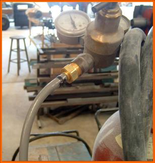
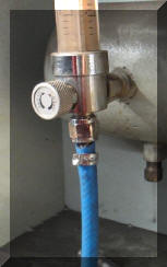
An interesting side note from this bar joist manufacturer: When evaluating
the fittings they would need for their 45 MIG welders, it was observed that one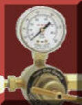 installation had
a low pressure "Gas Guard" regulator / flow control device mounted at the
feeder. It had an output pressure gauge calibrated in CFH (Photo Right). The maintenance manager indicated these had been installed on all welders
several years before at a
cost much higher than the
GSS and had to be removed due to inconsistent results. The one
remaining was
adjusted at a very high flow rate according to the flow gauge reading. The maintenance
manager indicated it would not be
reinstalled and was surprised it was still there!
See information that defines why they probably experienced these problem! installation had
a low pressure "Gas Guard" regulator / flow control device mounted at the
feeder. It had an output pressure gauge calibrated in CFH (Photo Right). The maintenance manager indicated these had been installed on all welders
several years before at a
cost much higher than the
GSS and had to be removed due to inconsistent results. The one
remaining was
adjusted at a very high flow rate according to the flow gauge reading. The maintenance
manager indicated it would not be
reinstalled and was surprised it was still there!
See information that defines why they probably experienced these problem!
See
another report from a welding engineer who had to remove 32 low pressure devices
from his production lines.
Unfortunately we have had other potential
users of our GSS not want to try the
system because of poor experience with other "gas saving products" causing weld
or welder acceptance problems. Although the patented
GSS is very simple it
does not create the problems caused by a number of other devices. It does
not alter the delivery pressure so automatic flow compensation is maintained.
Unlike simple orifices that restrict flow it does provide a controlled amount of
extra shielding gas at the weld start. The welder still has control of the
flow, it does not limit their ability to set the flow needed. They don't
have to "drill out" a flow limiting orifice!
(If
your welders are setting excessive flow rates, see our Flow Rate Limiter
Product.)
BE CAREFUL SOME OF THESE
DEVICES DO NOT MENTION THAT THEY LOWER PRESSURE!! ALSO ANY DEVICE THAT
MOUNTS DIRECTLY AT THE FEEDER WILL NOT PROVIDE SUFFICIENT EXTRA START GAS.
EMAIL IF YOU HAVE A QUESTION ABOUT A SPECIFIC MODEL
See
Another Bar Joist
Company Survey where they mounted flowmeters at the wire feeders to reduce
surge. They had insufficient extra gas at the start and used increased
flow rates to try to compensate - wasting gas!
|
|
Production Example Case 7
Texas Truck Storage Box Manufacturer Welds 2.7
Times More Parts with Gas Saver System; a 63% Gas Savings
 A Texas based
manufacturer of various types of truck storage boxes purchased a 25 foot Gas
Saver System (WAT FB25) to check for shielding gas savings. They picked a
repetitive job, welding doors, and started with a full cylinder of gas.
Welding with 0.035 solid wire MIG, using their standard gas delivery hose, 236
doors were completed with that cylinder. Putting on a new cylinder and the
GSS,
632 doors were welded before the cylinder was empty! That is 2.7 times
more parts. A Texas based
manufacturer of various types of truck storage boxes purchased a 25 foot Gas
Saver System (WAT FB25) to check for shielding gas savings. They picked a
repetitive job, welding doors, and started with a full cylinder of gas.
Welding with 0.035 solid wire MIG, using their standard gas delivery hose, 236
doors were completed with that cylinder. Putting on a new cylinder and the
GSS,
632 doors were welded before the cylinder was empty! That is 2.7 times
more parts.
The
gas savings can be stated several ways. In the base test, with the normal gas delivery hose 300 CF of gas
was consumed welding 236 parts. With the
GSS
they consumed only 300 CF x 236/632 = 112 CF for that same number of parts.
Therefore 300 CF-112 CF = 188 CF is wasted with their normal system! And the
GSS
still provides the proper amount of extra gas at the weld start and maintains
the pressure in the hose to automatically compensate for restrictions.
Calculating the gas savings
as a percentage of prior use; (300 -112)/300 = 63% gas savings.
Or said another way it takes 300/112 = 268% more gas to weld the same
number of parts. After these impressive results, 25
GSS's were purchased for the whole shop.
  Stated
another way; to weld 632 doors with their standard system theywould have needed 2.7 cylinders versus one with the
GSS !! Stated
another way; to weld 632 doors with their standard system theywould have needed 2.7 cylinders versus one with the
GSS !!

After several years of use they needed
another 10
GSS's
for new MIG welders.
They asked for more "Magic
Hose!"
|
|
Case 8
Pipe Fabricator Saves 41%
in Shielding Gas; Installs 215 Systems
 A Mid West Pipe
Fabricating Shop tested a number of systems to determine how much shielding gas
could be saved while maintaining their high quality standards. The
Gas Saver System came out on top with 41% gas savings. A Mid West Pipe
Fabricating Shop tested a number of systems to determine how much shielding gas
could be saved while maintaining their high quality standards. The
Gas Saver System came out on top with 41% gas savings.
They selected a
repetitive job for the test. With their standard gas delivery hose they used 32
pounds of flux cored wire with a full cylinder . With the
GSS
installed and a new cylinder, with all
the same welding conditions and part, 53 pounds of weld metal were
deposited! That calculates to a 41% gas savings. The
GSS
also supplied a controlled amount of extra gas on weld initiation for quality
starts and retained the ability to automatically compensate for flow
restrictions (which
low pressure systems do not!) Since their test was made with a
shorter gas delivery hose than will be required on most weld stations, their gas
savings will be even greater!
This shop uses a
number of dual MIG feeders to handle, for example, solid steel wire on one side
and stainless on the other. Both may require different gas mixtures.
A TIG system is included on many stations for root welds etc requiring a
different shield gas. For many of the weld stations that means
three separate gas lines running about 25 feet back to their respective gas
supply .
They purchased 115
GSS's
to equip their whole shop.
Two years later they expanded their operation and
ordered 80 more systems and another 20 in December 2012 after 4 more
years. When placing the last order it was mentioned they were very pleased
with the gas savings results and the durability of the
GSS.
|
|
Production Example Case 9
Major Trailer
Manufacturer Saves 25% in Production
Installs 71 Systems
A major US producer
of Trailers purchased two 25 foot Gas Saver Systems to evaluate in one of their
production plants. They found significant savings in their test
and purchased a total of 71 systems. Six months later they report a
shielding gas savings of 25% in production. They are now
broadcasting the word to their other plants.
With Argon price
increases of 25 to 40% publicly announced over the past 2 year this allowed cost containment to
maintain their competitive edge.
|
|
Production Example Case 10
6 Foot Delivery Hose Can Still Save 25 to
40+% Shielding Gas
 A
manufacturer of automotive exhausts uses over one hundred Robot Welders.
They have only a 6 foot shielding gas hose from the flow control at the gas
source to solenoid! After a number of tests of the Gas Saver System (GSSTM)
conducted during a Black Belt Lean Manufacturing Study
they measured from 25 to 40+% shielding gas savings depending on the
specific weldment. They have installed
GSS's on all 128 of their
Robotic Welders! They recently installed our patented
Flow
Rate Limiter and Lock to control the flow set on
their pipeline flowmeters. This device fits most US made
flowmeters and regulator/flowmeters. A
manufacturer of automotive exhausts uses over one hundred Robot Welders.
They have only a 6 foot shielding gas hose from the flow control at the gas
source to solenoid! After a number of tests of the Gas Saver System (GSSTM)
conducted during a Black Belt Lean Manufacturing Study
they measured from 25 to 40+% shielding gas savings depending on the
specific weldment. They have installed
GSS's on all 128 of their
Robotic Welders! They recently installed our patented
Flow
Rate Limiter and Lock to control the flow set on
their pipeline flowmeters. This device fits most US made
flowmeters and regulator/flowmeters.
In addition, the controlled
amount of shielding gas delivered at the weld start, at a flow rate that does not
pull air into the gas stream, can eliminate the need for preflow.
Preflow is sometimes used in an attempt to circumvent initial high gas surge causing
air aspiration and resulting inferior weld starts. This is
particularly a problem with Pulsed MIG welding. With the
GSS optimum starts are achieved
without wasting valuable cycle time and shielding gas.
Since the
GSS retains gas delivery pressure, automatic flow
compensation is maintained. This is critical in Robotic Welding operations where
high duty cycles can clog welding torch gas passages with spatter and debris from the
welding wire. A reduction in flow occurs if
this feature is not maintained (as occurs with low pressure
systems See
Details of This Feature.)
Another
Robotic Welder User Purchases 60
GSS's

A manufacturer of automotive
seats installs 60
GSS systems. They also have short gas
delivery hoses on their Robotic Welders and find the gas savings very
significant.
Robotic users show that
even with a short gas delivery hose, the standard size provides excess
shielding gas and excess gas flow at the weld start. |
|
Production Example
Case 11
350 Gas Saver Systems Purchased by Military Sub Supplier
A
manufacturer
supplying fabricated steel and aluminum parts for use in military components
purchased 350
GSS's as they switched from cylinder to pipeline
shielding gas supply. They evaluated the
GSS and in addition to shielding gas savings they found the hose was very rugged and well suited to
their tough environment. They needed new hose to connect to their
pipeline. Since our
GSS did not cost much more then conventional hose they
followed our "Just Do It" statement in our PayBack
calculation page (CLICK TO SEE).
They understood its ability to reduce gas waste since they were aware of the
gas surge that occurred with their cylinder gas supply. With the
higher pipeline pressures the gas waste caused by the start surge could be 50%
higher. The
GSS saves 80+% of the gas waste and improves weld
starts. It provides a controlled amount of extra gas at the start to
quickly purge air from the weld zone and torch nozzle. The starting
gas flow rate is controlled to prevent air from being pulled into the
shielding gas stream. Pipeline pressures would be above the 25 psi
minimum required to maintain automatic flow compensation.
|
|
Production Example Case 12
Texas
Hydraulics Saves 35% with Flow Rate Limiters

See Texas Hydraulics shielding gas savings and weld quality improvement
article published in the December 2006 issue of Trailer Body Builders
Magazine.
CLICK HERE or on Photo of Magazine Cover
 Texas Hydraulics
utilizes MIG Welding to fabricate hydraulic cylinders with bores ranging
from 1 inch to 15 inches; with some 20 feet long. Doug Watkins,
Welding Engineer for their Texas plants, found their welders were able
to adjust flowmeters at any time at a shielding gas flow beyond the range of
their Welding Procedure Specification (WPS). Some were found with the
flow measurement ball pinned to the top of the flow tube. Mr. Watkins
indicates, “We have found with our flowmeters that can mean a flow rate of
100 CFH or higher is being used. In addition to the gas waste, any flow
setting beyond about 50 CFH with our electrode extension pulls air into a
turbulent gas shield. That air creates weld spatter and possibly internal
(or even external) weld porosity.” Texas Hydraulics
utilizes MIG Welding to fabricate hydraulic cylinders with bores ranging
from 1 inch to 15 inches; with some 20 feet long. Doug Watkins,
Welding Engineer for their Texas plants, found their welders were able
to adjust flowmeters at any time at a shielding gas flow beyond the range of
their Welding Procedure Specification (WPS). Some were found with the
flow measurement ball pinned to the top of the flow tube. Mr. Watkins
indicates, “We have found with our flowmeters that can mean a flow rate of
100 CFH or higher is being used. In addition to the gas waste, any flow
setting beyond about 50 CFH with our electrode extension pulls air into a
turbulent gas shield. That air creates weld spatter and possibly internal
(or even external) weld porosity.”
By installing 30 WA Technology Flow Rate
Limiters (WAT FRLL) and limiting
the maximum flow that can be set, they assured a quality shielding gas
stream and eliminated gas waste. The maximum flow rate is now set at 40 CFH
and this setting locked-in. After an initial gas use audit, the calculated
shielding gas savings was measured at 25%. With follow up audits the actual
savings exceeds 35%.
Texas Hydraulics also has begun changing
its shielding gas delivery hoses to the Gas Saver
Systems. During their initial testing they showed an 18% reduction
in shielding gas use with less initial gas surge.
According to Mr. Watkins, “By using the
Flow Rate Limiters we are building a quality product and controlling our
consumable cost which continues to be more valuable every day. By switching
to the new Gas Saver Systems we expect to show greater than 20% additional
savings due to the frequent starts and stops. I really appreciate your
companies’ assistance; it helps me do better at my job. WA Technologies has
contributed directly to helping us control our cost in welding consumables
and help us remain competitive in our effort to provide the best product for
the right price.”
|
|
Production Example Case 13
Fabricator in Mexico Saves
30% and 42% Shielding Gas with GSS and Purchased 115 Systems
 A
fabricator making chillers in Mexico (who is part of a large US based
company) saw the need to reduce shielding gas waste and improve weld
quality. The welding engineer tested a12 foot
GSS on
several jobs to see what savings they might achieve. The savings
ranged from a low of 30% and a high of 42% easily justifying the investment.
They now have 115 systems and will enjoy the benefits. They also make
excellent use of our Portable Flowmeter (
WAT PFM ) to check flow at the inlet
to their wire feeders and then at the torch. They recently found a
significant flow reduction caused by a clogged torch. Even after
changing the liner the flow loss was still excessive. Replacing the
torch with a new one solved the problem! A
fabricator making chillers in Mexico (who is part of a large US based
company) saw the need to reduce shielding gas waste and improve weld
quality. The welding engineer tested a12 foot
GSS on
several jobs to see what savings they might achieve. The savings
ranged from a low of 30% and a high of 42% easily justifying the investment.
They now have 115 systems and will enjoy the benefits. They also make
excellent use of our Portable Flowmeter (
WAT PFM ) to check flow at the inlet
to their wire feeders and then at the torch. They recently found a
significant flow reduction caused by a clogged torch. Even after
changing the liner the flow loss was still excessive. Replacing the
torch with a new one solved the problem!
They are also evaluating our new
Flow Rate Limiter.
|
|
Production Example
Case 14
Manufacturer of
Irrigation Pipe Saves Over 40% and Installs 120
GSS's
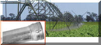 A
company welding pipe flanges on various diameter irrigation pipe evaluated
the
GSS to determine what shielding gas savings they could
achieve. A
company welding pipe flanges on various diameter irrigation pipe evaluated
the
GSS to determine what shielding gas savings they could
achieve.
Although the 120 MIG welders in the
shop are on pipeline gas supply they employed several cylinders of the same
shielding gas to get accurate usage measurements. Utilizing a
regulator/flowmeter having a pressure equal to their pipeline pressure
provided convincing results. On one size pipe they were able to weld 139
more joints with the
GSS installed with a full cylinder compared to their
standard gas delivery hose. On a larger diameter pipe 79 more flanges were
welded. Overall they achieved over a 40% reduction in gas use. The payback
was easily justified and they purchased systems for all their MIG welders.
Want to evaluate a GSS
for your application?
-
Just measure the
length of your existing gas delivery hose from feeder to gas supply and
order a similar length GSS.
-
If on cylinder gas
supply just be sure to use the same brand/model regulator/flowmeter of
flowgauge/ regulator if you’re going to use more than one weld station for
comparison. Compare the number of similar weldments made with existing
and
GSS or measure the weight of wire used with a full
cylinder with each system and obtain pounds wire used per cylinder of gas.
-
If you’re on bulk
gas supply simply purchase two cylinders of the same gas your currently
using. Use regulator/flowmeters that have the same outlet pressure when
welding stops as your pipeline pressure. Email if you want to know which
to purchase.
|
|
Production Example Case 15
Bucyrus
Machinery China Orders Fitted
GSS's
After several months
of use a Second Order was placed. They now have 50 systems.
Bucyrus Langfang
Machinery Co. Ltd in China
(now part of Caterpillar Tractor) sent pictures of the hose fittings on their wire feeders and flowmeters. As expected
they were not CGA 032 "B" inert gas fittings. They asked how they
should order fitted GSS's. The
answer- just order the lengths needed and send an email
 or
note with the order-"Splice Fittings Required Both Ends." We sent fitted FB or
note with the order-"Splice Fittings Required Both Ends." We sent fitted FB
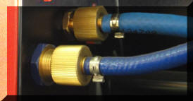 hoses
with splice fittings (as shown in the photo above right.) The fitting on the
feeder end included a peak flow limiting orifice. They simply spliced
into their feeder and flowmeter hoses by cutting them about 2 inches from
the existing fittings and inserting the hose barbs supplied with the
GSS. Gas savings performance is the
same as with standard CGA 032 fittings. hoses
with splice fittings (as shown in the photo above right.) The fitting on the
feeder end included a peak flow limiting orifice. They simply spliced
into their feeder and flowmeter hoses by cutting them about 2 inches from
the existing fittings and inserting the hose barbs supplied with the
GSS. Gas savings performance is the
same as with standard CGA 032 fittings. |
|
Production Example Case 16
 A
manufacturer of fabricated steel products related to compacting, storing and
transporting waste has production facilities in many locations. After
testing for savings, six of the plants have installed 288 GSS's. Gas savings tests showed from
41 to 47% savings with some performed with shorter gas delivery hoses
than used in production. Longer gas delivery hose lines create greater
shielding gas losses and therefore
yield more savings when GSS's are
installed. The initiative to purchase for all the plants is of
interest and came from: A
manufacturer of fabricated steel products related to compacting, storing and
transporting waste has production facilities in many locations. After
testing for savings, six of the plants have installed 288 GSS's. Gas savings tests showed from
41 to 47% savings with some performed with shorter gas delivery hoses
than used in production. Longer gas delivery hose lines create greater
shielding gas losses and therefore
yield more savings when GSS's are
installed. The initiative to purchase for all the plants is of
interest and came from:
 |
In 2010, one plant manger, after seeing our web
site, purchased a GSS and
conducted gas savings tests. He purchased 44 for all his MIG welders
(Note they purchased another 12 for new MIG welders in 2012.) |
|
The regional president told each plant in his
area to
purchase a GSS and conduct their
own tests! We worked mostly with the plant managers who knew they
would be asked by the corporate president about their results. There
were careful to set their tests to get accurate results. That is
how we were able to obtain the excellent savings results data. |
|
The manager of Operational Excellence for the
company was also helpful. |
Note: In 2012, two plants ordered
another 1000 feet of GSS hose with
fittings. |
|
|


