|

Since the Invention of TIG and MIG Welding, Flow Control Systems Have Used Gas
Pressures Above 25 psi
-- For Good Reason!
|
|
HOW CONVENTIONAL REGULATOR/ FLOWMETERS WORK |
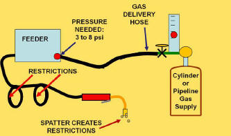 When gas is flowing, a
needle valve reduces pressure to 3 to 7 psi needed flow 30 to 40 CFH.
The specific pressure required depends on the amount of spatter in the MIG gun nozzle and gas diffuser as well as gun cable restrictions,
etc. When gas is flowing, a
needle valve reduces pressure to 3 to 7 psi needed flow 30 to 40 CFH.
The specific pressure required depends on the amount of spatter in the MIG gun nozzle and gas diffuser as well as gun cable restrictions,
etc.
Flow will remain at the
desired preset level even with restriction variations if a principle called
"choked flow" is employed.
|
|
 Choked flow relies on the fact that gas velocity through a small
opening can not exceed the speed of sound. If
the absolute pressure upstream of a needle valve (or an orifice) is twice
the downstream pressure, choked flow occurs. With choked flow, the
downstream pressure (i.e. restriction variations) does not effect flow rate. Note 5 psi = 20 psia (abso Choked flow relies on the fact that gas velocity through a small
opening can not exceed the speed of sound. If
the absolute pressure upstream of a needle valve (or an orifice) is twice
the downstream pressure, choked flow occurs. With choked flow, the
downstream pressure (i.e. restriction variations) does not effect flow rate. Note 5 psi = 20 psia (abso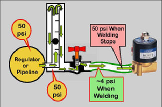 lute pressure) then 2 x 20 psia = 40 psia. 40 psia - 15 psi = 25 psi, the minimum regulator or pipeline pressure needed to achieve choked flow. lute pressure) then 2 x 20 psia = 40 psia. 40 psia - 15 psi = 25 psi, the minimum regulator or pipeline pressure needed to achieve choked flow.
Consider a typical 50 psi
pipeline gas supply. When welding, the needle valve reduces the 50 psi pipeline
pressure to the 4 to 5 psi average needed to flow the desired rate of shielding gas.
However when welding stops, flow continues through the needle valve and quickly fills the delivery
hose with excess gas at 50 psi.
|
|
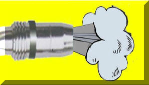 The excess gas stored
when welding stopped, blasts out of the MIG gun nozzle every time welding
starts. It can be 7 times the physical hose volume due to the
increased pressure. This The excess gas stored
when welding stopped, blasts out of the MIG gun nozzle every time welding
starts. It can be 7 times the physical hose volume due to the
increased pressure. This 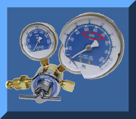 causes significant gas waste and also inferior starts
due to the moisture laden air pulled into the turbulent gas stream created
by the high flow. causes significant gas waste and also inferior starts
due to the moisture laden air pulled into the turbulent gas stream created
by the high flow.
Regulator/Flowgauges (where
output pressure gauge is calibrated in CFH) operate by setting pressure
above a very small (~0.025 inch diameter) flow control orifice. They
use pressures from 30 to 80 psi; above that needed for "choked flow"
and "Automatic Flow Compensation." When welding stops, the 3
to 7 psi in the gas hose raises to the upstream pressure of 30 to 80 psi
causing similar gas waste to flowmeters. |
|
Tests Conducted To Check How Well a 25 psi
Regulator/Flowmeter Maintains Flow Compared to a Low Pressure "Surge
Reducing" Regulator
 FLOW
TESTS: The following table provides test results with a
conventional FLOW
TESTS: The following table provides test results with a
conventional
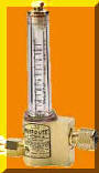
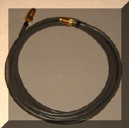
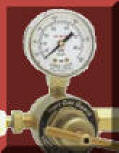 regulator flowmeter (photo left) and a commercial
"Gas Guard" low pressure regulator
(photo right) subjected to varying
restrictions. Both were initially set to flow 31 CFH as noted in
Blue. Gun restrictions were
then added and removed (as if the gas ports were alternately clogged and
cleaned) to vary the amount of restrictions. The resulting flow rates are shown in the table below.
the measured flow rates were validated with calculations: regulator flowmeter (photo left) and a commercial
"Gas Guard" low pressure regulator
(photo right) subjected to varying
restrictions. Both were initially set to flow 31 CFH as noted in
Blue. Gun restrictions were
then added and removed (as if the gas ports were alternately clogged and
cleaned) to vary the amount of restrictions. The resulting flow rates are shown in the table below.
the measured flow rates were validated with calculations:
|
| Flow Control System |
<
Typical Production Restriction Range
> |
|
3 psi |
4 psi |
5 psi |
6 psi |
7 psi |
8 psi |
| Conventional = 25 psi |
31 CFH |
31 CFH |
31 CFH |
31 CFH |
31 CFH |
31 CFH |
| Low Pressure; 9 psi |
37 CFH |
34 CFH |
31 CFH |
27 CFH |
23 CFH |
16 CFH |
|
The Conventional 25 psi System maintained the preset desired level of 31 CFH even when the
restrictions in the feeder/torch system ranged as low as 3 psi to as high as 8
psi, the typical range found in production.
The Low Pressure System was a
commercial low pressure regulator device. The gas flow was set
at 31 CFH at the nominal 5 psi restriction in the system and then locked
in place. However the flow varied from 16 CFH to 37 CFH as restrictions
were added and removed from the system. The flow
calibrated pressure gauge included with this device read
31 CFH for all the tests! This gives
the false impression that the flows remained constant. The flow range
would be well out of that defined in any Welding Procedure Specification!
No wonder welders set the flow rate, as measure by the gauge, much
higher than management believes is necessary! Not understanding the
problem frustrates welders and managers! |
|
 Be
careful, some of these low pressure devices do not mention they use low
pressure! They may just say "reduce surge," "Gas Guard," or some such wording.
EMAIL IF YOU HAVE A QUESTION ABOUT A SPECIFIC MODEL. Be
careful, some of these low pressure devices do not mention they use low
pressure! They may just say "reduce surge," "Gas Guard," or some such wording.
EMAIL IF YOU HAVE A QUESTION ABOUT A SPECIFIC MODEL.
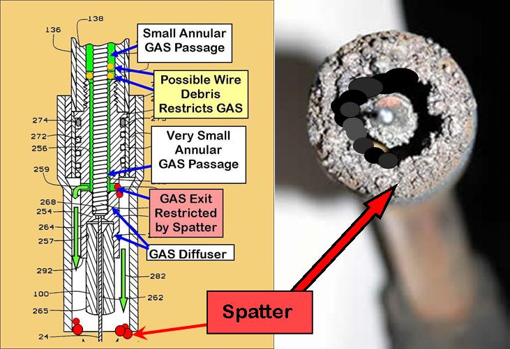
Where do restrictions
come from in production? Spatter in the gun nozzle is the easiest to
see. However spatter in the small gas diffuser holes creates even
higher levels. Also the gas passage in the gun cable often doubles as
spiral wire liner passage and can clog with copper flakes and wire drawing
lubricant. |
|
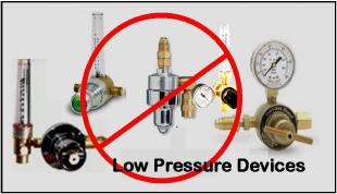
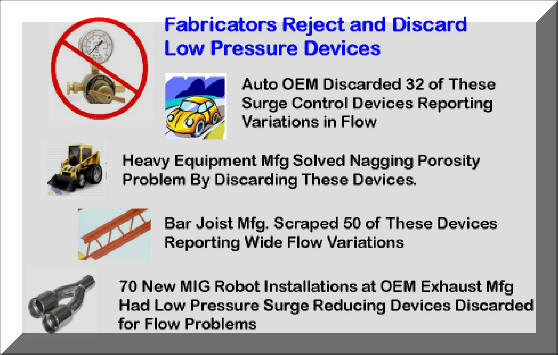
Some fabricators
expressed reluctance to try our unique patented
GSS since they had tried the more expensive low pressure
devices which did not work and only frustrated their welders! Our
tests showed why they were frustrated! Four, shown in the figure below, reported discarding several hundred of the same low pressure device
we tested! |
|
 |
|
 BENEFITS OF THE
PATENTED
GSS BENEFITS OF THE
PATENTED
GSS
Our
WA Technology
GSS
saves shielding gas waste by reducing the volume of gas stored in the gas
delivery hose and utilizing a flow restrictor at the wire feeder end of the
hose. It does not alter the pressure and therefore the flow
compensating feature of the regulator/flow device being used.
Hose restrictions
from spatter or caused by crimping or kinking of the MIG gun cable, are
compensated for without the welder having to interact with the system.
The
GSS
surge flow restrictor size allows the welder to control rate within usable limits. However if they are setting excessively high flow rates (we have measured flows at the gun nozzle of 150 CFH when the needle valve is opened wide) the GSS will limit the flow to the level set by the peak flow orifice. By maintaining the original delivery pressure, a
controlled amount of extra gas flow is quickly available at the weld start to
displace any air which diffuses into the torch nozzle and hose when welding is stopped.
It also quickly provides extra gas to purge air from the weld start zone at a
flow rate that is not excessive causing air to be aspirated into the gas shield.
At typical shielding gas flow rates and for most gas delivery hose lengths the
small pressure drop in the
GSS
hose is easily handled.
With most gas delivery pipeline pressures and regulator/ the
GSS
can be used with hose lengths up to 75 to 100 feet. However for lengths
above 50 feet we recommend you contact us and define the pipeline pressure you
are using or if on cylinder supply the regulator model being employed.
|
|
|
WANT TO LOCK-IN FLOW SETTINGS?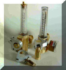
If
it is desired to lock the flow setting to prevent welders from
increasing set flow rates we have another patented product that allows
locking most brands and models of flowmeters, both pipeline and cylinders
types. Made from billet aluminum it slips over the flow control knob
after the maximum flow if set. A set screw locks it to the knob, no
alteration of the flowmeter is needed. The knob can not be turned
further in the direction of increased flow. An optional small brass
padlock prevents access to the set screw.
CLICK ON PICTURE ABOVE FOR DETAILS |
|
Still Have Questions About How With No
Moving Parts Automatic Flow Control Is Accomplished? CLICK HERE
CLICK to See Why Simple Orifices (or
other flow controls) Mounted at the Wire Feeder Reduce Surge But Create Less
Obvious But Significant Weld Problems
PURCHASE
GSS
PRODUCT
|


