Improving Quality of MIG Welds and Weld Starts Four Improved Start Quality Testimonials: |
|
1st Testimonial: GSS Eliminates Porosity We sent the Gas Saver System by Express Mail and it arrived the next day. He sent this email, “After putting the GSS hose on I have some of the best looking welds I've seen. I think out of 50 parts, I only had 2 or 3 to clean up. Thanks for the help.” |
|
"The GSS reduced the porosity problems previously encountered in several production cells." |
|
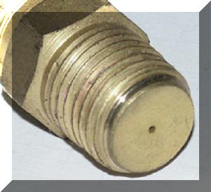
3rd: Jason Insley ordered a 3 foot GSS for his welder and after installing sent this note: "Everything worked fine. And my weld starts have definitely improved since installing the GSS. Thanks again." See details of the splice fitting we supplied for his Hobart Handler welder. |
|
4th: Al Hackethal reported GSS results in his shop: "Glad I found your website, I understood the theory, though in practice I understand it much better. I can't believe it. I'd never have thought a hose could make that much of a difference. I had a small job that had been waiting for a while. The weld quality is considerable better. Almost no splatter! I realized that the gas I'm buying is actually working the way it's supposed to. Thanks for making products affordable!” CLICK TO SEE more details and what Al said about the leather cable cover he also purchased! |
|
|
|
|
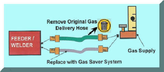
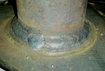
Our patented Gas Saver System (GSS) provides better weld start quality by eliminating the excess "GAS BLAST" at each weld start. It can also cut gas use in half by eliminating shielding gas waste. Many thousands are in use. |
|
|
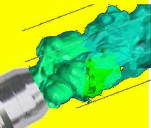
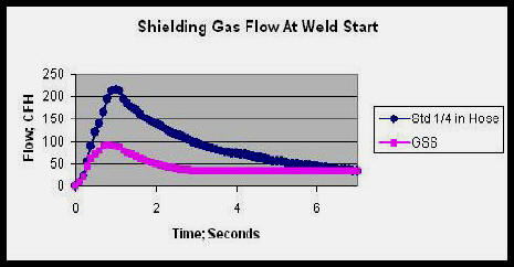
EXCESS GAS FLOW RATE CAUSES PROBLEMS:
At Each Weld Start a blast of shielding gas
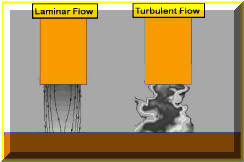
exits the MIG gun nozzle at very high flow rates with typical gas delivery systems. We have (Click on Graph for details of measurements made in a production application) Peak flow is well above the rate that creates turbulence in the shielding gas stream. This turbulence pulls moisture laden air into the gas stream creating poor shielding. The turbulence takes a short time to stabilize even after the flow returns to the preset level. This creates excess spatter and often internal, if not external weld porosity. The ideal starting gas flow control is shown by the graph labeled GSS. This limits the excess gas surge volume and peak flow rate while still providing extra gas needed to purge the MIG gun nozzle and weld start area.
|
|
 If
Excess Gas Flow Is Such Is A Problem, Why Has My Gas Supplier Not
Told Me? CLICK To SEE ANSWER. If
Excess Gas Flow Is Such Is A Problem, Why Has My Gas Supplier Not
Told Me? CLICK To SEE ANSWER. |
|
|
With solid steel MIG wires, some Oxygen can be tolerated. The silicon and manganese contained in the wire can combine with the Oxygen to form silicon and manganese oxide and avoid the carbon in the weld puddle forming a CO bubble. These oxides float to the weld surface. However published information indicates Nitrogen at levels less than 2% in the shielding gas can cause porosity in single pass welds (Reference ESAB, former L-TEC/ Linde MIG Welding Handbook; ".. 2% Nitrogen produced porosity in single pass welds made in mild steel; additions of 0.5% produced porosity in multipass welds." ) Unlike Oxygen, chemically combining Nitrogen into harmless compounds is not viable with solid wire. Elements like titanium can be employed but only at low levels since significant amounts cause embitterment. |
|
|
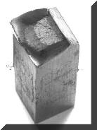
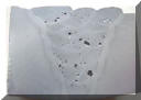
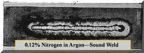
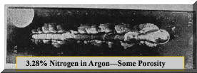
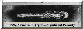
Weld Tests by Ludwig Quantify Nitrogen Problems: Visible evidence of the effect of nitrogen was reported by Ludwig in a Welding Journal Technical Paper (September 1955.) Typical of the quality research work done at the time, he employed a shielding chamber so the effects of turbulence in the shielding stream were eliminated as a variable. The following are some photographs of the more than 35 steel welds he made in an atmosphere of Argon with various amounts of Nitrogen added: |
|
|
|
|
|
|
Ludwig concludes in this 6 page research report: "no more than 1% Nitrogen should be allowed but preferably 0.5% ...it may be introduced from the atmosphere in proximity of the Argon shield." |
|
Air contains 78% Nitrogen; 5% contamination in the shielding gas stream due to turbulence gives 3.9% Nitrogen in the gas stream. That is sufficient to produce at least internal porosity. Be sure your getting what you pay for - SEE ARGON PURITY BELOW. |
|
|
INSUFFICIENT
EXTRA GAS AT THE WELD START ALSO A POOR SHIELDING PROBLEM: Excess gas flow rate at the weld start is bad but insufficient extra gas creates similar problems. This was stated best by Stauffer's 1982 patent. He clearly understood the problem and designed around it using a "surge storage tank"; he states in the patent teaching, "... air leaks back into the MIG gun and lines when welding is stopped. The air must be quickly purged and replaced with inert gas to produce high quality welds. Also, it is critical to displace the air at the weld zone of the work piece upon initiating the weld. " Some devices that attempt to reduce gas surge create a weld start problem. These devices set gas flow at the wire feeder such as simple orifices, regulators, flowmeters or needle valves. Welders often observe this lack of start gas needed to purge the air from the start area. They try to counter by increasing the steady state gas flow rate to achieve more gas at the weld start! But increasing the steady state flow still does not sufficiently purge the weld start area and just increases needed flow while welding, wasting gas! CLICK for More Information About Needing Extra Gas at the Weld Start? |
|
|
Eliminating Oxygen and Nitrogen at the weld start to reduce the possibility to weld porosity and excess weld spatter requires good shielding. In addition to Oxygen and Nitrogen the surrounding air contains Moisture or Water Vapor. The Water Vapor can also be drawn into the arc where it will disassociate into Oxygen and Hydrogen. Moisture can enter the gas delivery hose due to what is called permeation, migration through the hose to the shielding gas.
Hydrogen can cause more than porosity problems. Some amount can dissolve
in the molten steel and will only come out when the weld cools.
Since they are very small, Hydrogen atoms it can migrate through the steel
accumulating near defects, dislocations, etc. forming Hydrogen gas. This
can cause cracking.
These cracks may be in the weld itself or in the adjacent parent metal called
the heat affected zone.
If welding aluminum, hydrogen can cause porosity since similar to steel it is readily soluble in molten aluminum but not when it solidifies. GSS Hose Reduces Moisture and Gas Permeation A major Industrial Gas Producer, Air Products, proved the Gas Saver System (GSS ) reduced moisture permeation and purchased over 200 systems! They report after two summers of using the GSS on all welders they essentially eliminated the previous significant porosity problems they had always encountered in humid summer conditions! In fact our GSS hose reduces moisture and gas permeation (diffusion of moisture and gases into the hose) by up to10 fold! Want to know how?
|
|
|
PRODUCTION EXAMPLES OF PROBLEMS
CREATED WITH SOME DEVICES THAT CONTROL FLOW AT THE FEEDER: Case 1: Low Pressure Gas Control Device Mounted at Wire Feeder Caused Weld Quality Problems
After all this testing and
elimination of differences he found one of the ma This particular regulator flow control device used low pressure to control flow. This creates a double problem! In our tests of this device we found only 9 psi was needed to flow 31 CFH. With the range of flow restrictions found in production flows varied from 16 to 37 CFH while the flow calibrated pressure gauge read a steady 31 CFH (CLICK FOR TEST RESULTS.) In addition to the lack of sufficient start gas; variability in flow was probably allowing nitrogen to enter the shielding gas stream even when welding. If shielding gas flow rate is too high or too low this can occur. BE CAREFUL SOME OF THESE DEVICES SOLD TO REDUCE SURGE DO NOT MENTION THAT THEY USE LOW PRESSURE TO CONTROL FLOW ! ALSO ANY DEVICE THAT MOUNTS DIRECTLY AT THE FEEDER WILL NOT PROVIDE SUFFICIENT EXTRA START GAS. EMAIL IF YOU HAVE A QUESTION ABOUT A SPECIFIC MODEL. |
|
|
Case 2: Removing Orifice Mounted at Feeder Showed Benefits of Having a Limited Amount of Extra Gas at a Controlled Flow Rate at Weld Start:
If sufficient shielding gas is not
provided at the start, welders may try to compensate by using higher overall
gas flow. A bar joist manufacturer was using flow control orifices
mounted at the wire feeders. Argon/CO2 shielding gas is supplied in a pipeline
through about 15 feet of gas
A test was made to check weld performance and potential shielding gas savings using two cylinders of gas on two adjacent welders instead of their pipeline gas supply. One was set with their standard flow control orifice system and a regulator providing a pressure that matched their pipeline, 50 psi. The other with a regulator/flowmeter (also of a 50 psi design) using a 15 foot GSS without their flow control orifice. Both steady state flows were set at 45 CFH. Since welders stand side by side, it was easy to observe the weld start quality! Instantly the welder using the GSS noticed improved starting. After about an hour with observably better results the welding engineer suggested we lower the shielding gas flow on the welder with the GSS to 35 CFH! The same improved weld start quality was observed and the welder was "happy." In fact even though we lowered the steady-state flow to 35 CFH there was still about the same controlled amount of extra gas available at the start (that stored in the GSS hose when welding stopped.) The higher start gas flow rate established by the surge flow orifice in the GSS maintained the higher flow at the start. This higher start flow rate quickly flooded and purged the weld start area of moisture laden air. It was this air that was casing excess spatter and lack of shielding on all their other welders! After about 4 hours of observation it was obvious the spatter at the weld start was less with the GSS. We also measured a reduced use of shielding gas of 25%. After several months of testing to check this one system during windy days etc, this shop now has GSS's installed on all 50 welders! Bottom Line - - "Some extra gas flow at the start is very beneficial." In addition, after about a year of use their gas supplier called to see if their business had turned down since they were using about 30% less gas- it had not! Also note that any flow control device installed right at the feeder, be it an orifice flow control or a flowmeter will have the same lack of sufficient initial shielding gas to purge the weld start area. One of the major welding companies has been utilizing an oscilloscope and has documented the "Improved Arc Characteristics" at the weld start when using one of our Patented Gas Saving Systems. Note: Don't confuse our Patented Gas Saver System (GSS) with other devices that may have tried in the past. The GSS provides a controlled amount of extra gas at the weld start at a flow rate that avoids excess turbulence to properly purge air. It also does not alter system pressure so "Automatic Flow Compensation" is maintained. Welders Love The Improved Starting Results! SEE DETAILS |
|
|
Case 3: Recent Example Quantified Lack of Start Gas Problem A review of the shielding gas flow rates in a shop with 100 welders revealed the amount of excess gas flow on each welder. DETAILS:
A shop with ~100 MIG welders tried to
reduce gas waste As when mounting an orifice at the wire feeder, this approach eliminates the start surge flow but there is insufficient extra gas available to purge air from the weld start area and MIG gun nozzle. It is if you're starting in air! As expected, the welders tried to compensate by increasing the steady state flow, which they really can not fully accomplish!
The following was observed: Conclusion: As we have seen in the past, in trying to compensate for the lack of sufficient extra start gas, the welders set the steady state flow far higher than needed. Any flow over 50 to 60 CFH is just pulling air into the gas stream and is counter productive!
Although similar in appearence to the Gas Guard discussed above these both operate at above 25 psi so retain "automoatic flow compensation" built into quality gas flow control systems, since the process was introduced in the 1950's. However like a simple orifice mounted at the wire feeder that lack the needed gas to purge air from the weld start area.
SOLUTIONS: There are several ways to solve this problems: 1) Put the flowmeters or flow control devcie back at the pipeline and install our inexpensive patented Gas Saver System (GSS.) The limited amount of extra gas stored in the GSS hose when welding stops provides sufficient extra start gas at the weld start at a peak flow rate that avoids excess turbulence. 2) One of our recent patents defines a method to mount a flow control near the wire feeder but also incorporates a controlled volume of storage and uses a peak flow ratelimiting orifice. It controls the steady state flow at a selectable fixed rate. It was designed for portable wire feedrs as used in a shipyard wire where the gas delivery hose could be 200 feet long, or more. Visit This Page for Details of this Orifice Flow Control System IF INTERESTED IN MORE DETAILS OF ANY OF THESE APPROACHES - EMAIL
|
|
|
Argon is 0.9% of air. It is generally produced by liquefying air and separating the Argon in a elaborate, expensive distillation column. However Argon can be produced at lower cost and quality levels and is referred to as "Crude Argon." Crude Argon may contain about 2% Oxygen. For most steel welding applications that may not present problems. However "Crude Argon" contains Nitrogen perhaps about 0.5% ! That is a problem. Even if the Nitrogen percentage is lower, when combined with moderately turbulent shielding Nitrogen porosity can result.
The American Welding Society produces a
"Specification For Welding Shielding Gases; AWS A5.32." It defines the
Minimum Purity of Gases to be labeled as meeting the AWS standard. It
can be obtained at
www.awspubs.com That specification defines the
Minimum Purity for Argon as 99.997%. That would allow no more than
0.003% Nitrogen if no Oxygen or other gases were present. It also defines the Maximum
Moisture at 10.5 ppm (= 0.00105%.) There is no reason to get
less- that's what you pa
WARNING The AWS Document also warns that Argon and Carbon Dioxide are heavier than air and may concentrate in low areas such as the bottom of pressure vessels, tanks, pits and ships. This can result in asphyxiation and death. See our page on "Weld Safely" |
|
|
We did also. We found out why the same weldment achieved 45 ft-lbs and 7 ft-lbs in the same deposit! Want to know why?
|
|
|
Saving Shielding Gas and Improving Weld Start Quality is Easy... "Just Replace Existing Gas Delivery Hose with Our Gas Saver System"
|
|
 Want to Limit the Maximum Flow Rates That Can be Set? Check out our newly patented Flow Rate Limiter and Lock. It allows the maximum allowable gas flow to set and locked. It fits most Flowmeters and regulator/flowmeters without alterations. |
|
|
Want a way to control the maximum shielding gas flow that can be used? SEE "Lean Welding Manufacturing" Learning Program Optimizing Shielding Gas Use and Eliminating Waste
|
|

|
|
|
|
|
| ▲ HOME |
|
 An Argyle TX fabricator, Brad Fenley called requesting
a 6 foot long (FB6) Gas Saver System (
An Argyle TX fabricator, Brad Fenley called requesting
a 6 foot long (FB6) Gas Saver System ( 2nd: Caterpillar Tractor plants have a number of GSS's installed in several plants, one reported:

 A
Welding Engineer at a major Midwest heavy construction equipment company
was having porosity in the same weldment in one plant and not in another.
He performed a very careful, systematic analysis of the problem.
A fishbone troubleshooting diagram was developed with over 30 items
considered in attempt to solve the problem. It appeared to be a
nitrogen porosity problem so he looked at all the possible causes. He checked for
pipeline, solenoid, feeder plumbing leaks, putting on cylinder gas supply to validate the quality of
shielding gas and many others items. He even tried a different type and
manufacturer of the solid wire they were using.
A
Welding Engineer at a major Midwest heavy construction equipment company
was having porosity in the same weldment in one plant and not in another.
He performed a very careful, systematic analysis of the problem.
A fishbone troubleshooting diagram was developed with over 30 items
considered in attempt to solve the problem. It appeared to be a
nitrogen porosity problem so he looked at all the possible causes. He checked for
pipeline, solenoid, feeder plumbing leaks, putting on cylinder gas supply to validate the quality of
shielding gas and many others items. He even tried a different type and
manufacturer of the solid wire they were using. 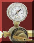 jor
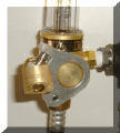
causes was the plant
with the porosity problem was using low pressure surge reducing
devices (Gas Gurad) on their wire feeders (photo right.) These controlled flow at the
feeder providing insufficient extra gas to purge the MIG gun nozzle and weld
start area of moisture laden air. These were removed and the
problems went away!
jor
causes was the plant
with the porosity problem was using low pressure surge reducing
devices (Gas Gurad) on their wire feeders (photo right.) These controlled flow at the
feeder providing insufficient extra gas to purge the MIG gun nozzle and weld
start area of moisture laden air. These were removed and the
problems went away! 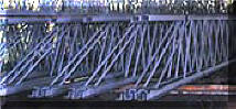 delivery hose. The flow control orifice
established the flow at 45 CFH. However the welders wanted higher flow
rates with some even drilling out the orifice! The welding engineer wanted to avoid wasting
shielding gas. With this flow setting arrangement where control is mounted at
the feeder there is insufficient extra gas provided at the weld start.
This lack of extra gas prevents to purging the weld start area of
moisture laden air.
delivery hose. The flow control orifice
established the flow at 45 CFH. However the welders wanted higher flow
rates with some even drilling out the orifice! The welding engineer wanted to avoid wasting
shielding gas. With this flow setting arrangement where control is mounted at
the feeder there is insufficient extra gas provided at the weld start.
This lack of extra gas prevents to purging the weld start area of
moisture laden air.
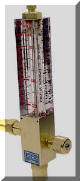 by installing flowmeters at the wire feeders. These were connected by a gas
hose to a 50 psi shielding gas pipeline. Most of the flowmeters were model L-32
(shown at right) which is designed and calibrated for 50 psi, so the flow readings
are direct and accurate.
by installing flowmeters at the wire feeders. These were connected by a gas
hose to a 50 psi shielding gas pipeline. Most of the flowmeters were model L-32
(shown at right) which is designed and calibrated for 50 psi, so the flow readings
are direct and accurate. 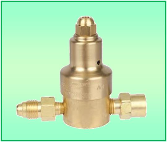
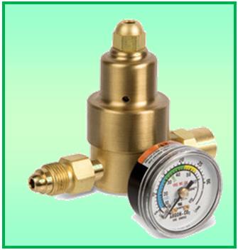 NOTE: Any device that controls the steady state gas flow at the MIG wire feeder has the same, "lack of needed gas to purge the weld start area." Two examples are the regulators shown on the left.