The Problem -
An orifice at the
outlet of a regulator or a
needle valve after a flowmeter are used to control the rate of shielding gas flow. With
Regulator/Flowmeters (Photo Below Left) outlet pressures range from 25 to 80
psi. Flowmeters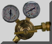 used on pipelines allow pipeline pressure to exit the flow control valve
when welding stops. A typical pipeline pressures 50 psi.
used on pipelines allow pipeline pressure to exit the flow control valve
when welding stops. A typical pipeline pressures 50 psi.
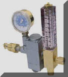 Flowgauge/Regulators (Photo Right)
operate by setting the pressure above a critical orifice. An outlet
pressure gauge is calibrated in CFH. For most MIG
shielding gas flow rates the pressure exiting the control orifice when welding
stops will range from 40 to 70 psi.
Flowgauge/Regulators (Photo Right)
operate by setting the pressure above a critical orifice. An outlet
pressure gauge is calibrated in CFH. For most MIG
shielding gas flow rates the pressure exiting the control orifice when welding
stops will range from 40 to 70 psi.
However the pressure needed at the feeder to flow the shielding gas though the solenoid, fittings and torch
can range 3 to 8 psi depending on torch length and restrictions that develop
while welding. The needle valve or orifice, if used, drops the pressure
to that low level when gas is flowing while welding.
When welding stops, gas continues to flow through the needle valve or
orifice and increases
pressure in the gas delivery until the
output of the regulator or pipeline is reached. Therefore the pressure in the gas
delivery hose will be about 25/3 =
8
to 80/3 =
26 times the pressure needed to flow
the desired amount of gas! For Flowgauge/Regulators 13 to 23
times what may be needed!
This extra pressure means there is much more gas stored
in the hose than it's physical volume.
When welding stops the extra pressure causes
This
Excess Volume of Shielding Gas to be stored in the
gas delivery hose between the flow control at the gas supply and the wire
feeder solenoid. Most of this excess gas volume is wasted every time the MIG torch switch is energized,
even when just inching the wire. The
excess can exceed the amount of gas used while welding! Inferior weld
starts result from the high gas surge flow pulling air into the shielding
gas stream.
How much excess gas can be stored
in a 1/4 inch delivery hose? Up to 7 times the physical
hose volume!
CLICK to See Why.
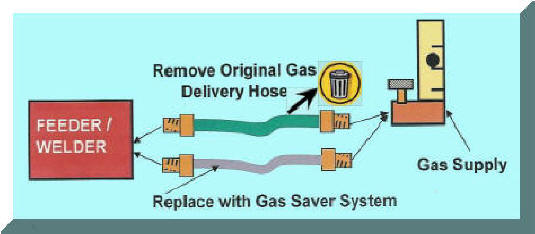
The
Solution - our Gas Saver System
(GSS)
eliminates the excess "gas blast" at the weld start. It retains and
delivers enough extra gas at a limited peak flow rate to purge the weld start area,
MIG gun nozzle and gun gas hose.


 The
GSS is a
Patented Gas Delivery Hose incorporating a Start Surge Limiter Orifice That Can Save 50%
or more of
MIG Shielding Gas Use and Improve Weld Start Quality.
The
GSS is a
Patented Gas Delivery Hose incorporating a Start Surge Limiter Orifice That Can Save 50%
or more of
MIG Shielding Gas Use and Improve Weld Start Quality. 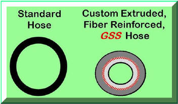 conventional
hoses and the use of a surge flow limiting orifice. The stored
gas creates another problem as it exits the torch with a high surge
flow at the weld start. Start gas flow
rates far exceed the level that allows smooth Laminar flow. It creates
Turbulent flow that pulls air into the shielding gas stream. The surge
flow restrictor incorporated in the
GSS not only adds to waste reduction (80 to 85% reduced gas surge,) it improves weld starts. The
start surge flow restrictor is sized so it does not limit normal gas flow settings. However if welders are setting very high flow rates (we have measured flows at the gun nozzle of 150 CFH with the knob opened wide) then the GSS will limit flow to the maximum peak flow level set by the orifice in the end fitting. This is about half the flow that can be set on a flowmeter, saving money and making higher quality welds.
conventional
hoses and the use of a surge flow limiting orifice. The stored
gas creates another problem as it exits the torch with a high surge
flow at the weld start. Start gas flow
rates far exceed the level that allows smooth Laminar flow. It creates
Turbulent flow that pulls air into the shielding gas stream. The surge
flow restrictor incorporated in the
GSS not only adds to waste reduction (80 to 85% reduced gas surge,) it improves weld starts. The
start surge flow restrictor is sized so it does not limit normal gas flow settings. However if welders are setting very high flow rates (we have measured flows at the gun nozzle of 150 CFH with the knob opened wide) then the GSS will limit flow to the maximum peak flow level set by the orifice in the end fitting. This is about half the flow that can be set on a flowmeter, saving money and making higher quality welds.