| Flow Rate
Changes With Pipeline Pressure |
|
Both
Flowmeters and
Flow Control Orifices alter flow
rate as pipeline pressure varies. Depending on the pipe size and
configuration, pipeline pressure changes occur as additional welding
machines are placed in use. Just how much does the flow change?
We conducted the following Laboratory tests to demonstrate these flow
changes. |
|
Want a Detailed Report
on the Following Test Data?
It includes a
table with correction factors to calculate actual from measured flow
when pipeline pressure varies.
CLICK HERE to Download FREE PDF Copy: |
|
 Alert
!! Alert
!!
Argon
Prices Doubled in the Past Several Years. Two European Companies ow have 77% of the US Production Capacity! It Will Remain in Short Supply -Expect Even Higher Prices!
(See Details in Video)
Time to "Lock" Your Flowmeters with Our Flow Rate Limiter.
The Flow
Rate Limiter (FRL) is our latest gas saving patent. It's
simple and does not alter the flowmeter. Just set the maximum flow
desired and slip the billet aluminum FRL over the control knob
so its stainless pin prevents further increases. Then tighten the
setscrew with included Allen wrench. An optional brass lock prevents
setscrew access.
CLICK Here or Picture for Details
Our FRL is a Perfect Compliment to Our
Gas Saver System (GSS.)
With Both You'll Save Over 50 to 60% of Shielding Gas Use! |
|
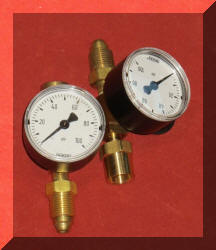
TEST PROCEDURE:
A pipeline flowmeter was connected to a
test pipeline that had its inlet pressure controlled by an inert gas regulator
connected to an Argon/CO2 shielding gas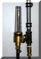 cylinder. The cylinder regulator allowed pipeline pressure to be varied from 20 to 75
psi. To assure pressure reading accuracy a calibrated 2 inch diameter gauge
was installed in the regulator outlet gauge port.
cylinder. The cylinder regulator allowed pipeline pressure to be varied from 20 to 75
psi. To assure pressure reading accuracy a calibrated 2 inch diameter gauge
was installed in the regulator outlet gauge port.
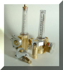
The flowmeter selected
for the test was a commonly used Victor* FM372 (photo right.) As noted in the Victor
literature, all their flowmeters are calibrated at 25 psi (accept one for CO2
which is calibrated at 80 psi to avoid ice particles in the needle
valve.) They note that the pressure is used to provide what we refer to
as "Automatic Flow Compensation"
that requires a pressure of 25 psi or greater. Therefore
the flow reading scale will only be accurate at a pipeline pressure of
25 psi. Increased pressure will produce a higher flow than what is
read on the flow tube. These Laboratory tests demonstrate just how much more
flow variation occurs with pipeline pressure changes with a fixed flow control knob setting. |
|
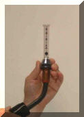
MEASURING ACTUAL FLOW:
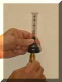 To
measure the actual flow we used a portable flowmeter, our part number
WAT- PFM. This uses the same flow
measuring principle defined by
Bernoulli in the 1700's. It is accurate and very repeatable. It was used in a way
recommended in our Lean Welding Manufacturing Self Study
Training Programs which is to measure flow with
the wire feeder gas hose fitting placed in the gauge (photo left.)
Therefore there is no possibility of leaks between the Victor FM372 and the
portable flowmeter. Instructions shipped with the WAT-PFM define how this
measurement approach in combination
with measuring at the MIG torch nozzle quantifies leaks in wire feeder plumbing, torch to feeder connections,
backflow through wire outlet guide etc and what differences are excessive. To
measure the actual flow we used a portable flowmeter, our part number
WAT- PFM. This uses the same flow
measuring principle defined by
Bernoulli in the 1700's. It is accurate and very repeatable. It was used in a way
recommended in our Lean Welding Manufacturing Self Study
Training Programs which is to measure flow with
the wire feeder gas hose fitting placed in the gauge (photo left.)
Therefore there is no possibility of leaks between the Victor FM372 and the
portable flowmeter. Instructions shipped with the WAT-PFM define how this
measurement approach in combination
with measuring at the MIG torch nozzle quantifies leaks in wire feeder plumbing, torch to feeder connections,
backflow through wire outlet guide etc and what differences are excessive.
As we do with each
batch of flowmeters, we checked the one used for these tests with calibrated
regulator/flowmeters placed on the cylinder. The WAT-PFM was accurate and correlated
with the regulator/flowmeters within our measurement precision from 20 to
40 CFH.
The following are the
results of the tests: |
| Pipeline
Pressure |
Reading on FM372 Flowmeter Flow Tube |
Published Correction Factor |
Flow Using
Correction Factor |
Actual Flow
Measured on Portable Flowmeter |
| 25 psi |
20 CFH |
1.00 |
20 CFH |
20 CFH |
| 30 psi |
23 CFH |
1.05 |
24 CFH |
23 CFH |
| 35 psi |
24 CFH |
1.12 |
27 CFH |
28 CFH |
| 40 psi |
26 CFH |
1.18 |
31 CFH |
32 CFH |
| 45 psi |
27 CFH |
1.23 |
33 CFH |
34 CFH |
| 50 psi |
31 CFH |
1.28 |
40 CFH |
40 CFH |
|
|
INTERPRETING TEST RESULTS:
Looking at the first
row of data. The pipeline pressure was set at 25 psi which is the
calibration pressure for the FM372 flowmeter. The 2nd column shows the
reading on the FM372 flowmeter which was 20 CFH since the flow knob was
adjusted to that flow setting. The next column is the published factor used to
correct for pressure differences between the actual pipeline pressure and
the calibration pressure. Since 25 psi is the calibration pressure
the factor is one. Therefore applying the factor shows 20 CFH in the
third column.
The last column is the flow measured on the WAT-PFM which, as expected, is also
20 CFH. This also validates the calibration of the
FM372 and the WAT-PFM flowmeter are the same. |
|
Examining the third row
of data; the pipeline pressure was raised to 35 psi with NO CHANGE IN
THE INITIAL
FLOW KNOB SETTING. The FM372 flow now read 24 CFH. The published correction
factor for the increase in gas density is 1.12. Applying this
correction factor shows an actual flow for an observed 24 CFH reading to be 28 CFH.
Therefore although the gauge on the Victor FM372 was reading 24 CFH the
actual flow was theoretically 28 CFH. The extra flow is because the
density difference in the gas from the 25 psi calibration pressure and the
35 psi in the pipeline. The actual
flow as measured on the WAT-PFM was 27 CFH which is within our
measurement precision of the theoretical 28 CFH. |
|
Looking at the last
row of data. Pipeline pressure was raised to 50 psi and the FM372
flowmeter now read 31 CFH. The correction factor for 50 psi is 1.28
yielding a theoretical flow of 40 CFH (31 X 1.28) for a 31 CFH
FM372 flowmeter reading. The calculated flow is the same as the actual flow
measured on the WAT-PFM that was also 40 CFH. That is 29%
more actual flow then measured on the FM372 flowmeter [(40-31)/31=29%. ]
Therefore if this flowmeter (or any calibrated at 25 psi, as are many) is
operated at a pipeline pressure of 50 psi and gas flow set at a reading of 31 CFH
using the flowmeter scale, the actual flow would be 40 CFH! That is
29% more flow
than read on the pipeline flowmeter scale. Not only is this wasting
gas but it could exceed
the
allowable range defined in a Welding Procedure Specification (WPS.)
|
|
TEST OF FLOW CONTROL ORIFICE:
Similar tests were
conducted using variations in pipeline pressures with our Standard Flow Control
Orifice, OGSS-45. We
compared the theoretical flow rate based on orifice size and pressure with
that read on the WAT-PFM. Here are the results: |
|
Pipeline
Pressure |
Theoretical Flow
Based on Orifice Size and Pipeline Pressure |
Actual Flow
Measured on Portable Flowmeter WAT-PFM |
|
25 psi |
25 CFH |
25 CFH |
|
30 psi |
30 CFH |
30 CFH |
|
35 psi |
33 CFH |
33 CFH |
|
40 psi |
35CFH |
36
CFH |
|
45 psi |
40 CFH |
41 CFH |
| 50
psi |
45CFH |
44 CFH |
|
|
As seen from the data, the flow measured on the WAT-PFM through a OGSS-45
Flow Control Orifice is very predictable and within the measuring precision of the theoretical flow based
on orifice size, pressure and flow calculations. |
|
BOTTOM LINE:
 If
employing pipeline supplied shielding gas and using an Orifice to Control If
employing pipeline supplied shielding gas and using an Orifice to Control
 Flow,
a Portable Flowmeter is the way to verify the actual flow. The flow
through the Orifice changed about 8 CFH with a 10 psi pipeline pressure
change. This is as predicted by
"critical flow" flow equations. Flow,
a Portable Flowmeter is the way to verify the actual flow. The flow
through the Orifice changed about 8 CFH with a 10 psi pipeline pressure
change. This is as predicted by
"critical flow" flow equations.
When using a Flowmeter to control
shielding gas flow from a pipeline, when pressure
changed 10 psi the actual flow changed a similar 8 CFH.
Therefore pipeline pressure changes produced essentially the same flow variations in
both Flowmeters and with Orifices used to set flow.
Note: When using
Regulator/Flowmeters on cylinder shielding gas supply, these flow reading
variations DO NOT exist as the regulator maintains the proper calibration
pressure of 25, 50 or 80 psi.
Why Not Use a Cylinder Regulator/Flowmeter
on a Pipeline Supply
to maintain a fixed pressure?
Answer: Because it will not
maintain a constant pressure with only a 40 to 100 psi input! These
devices are designed to operate over a wide range of inlet pressure, from
2500 psi though about 200 psi and the accuracy of control even
decreases at the lower inlet pressures! Valve size, diaphragm size and
spring pressure are all designed to this wide pressure range, especially the
very high pressure. If you want to use a regulator, you must select
the proper type. See below, and email: |
|
 Check
Pipeline Pressure with our WAT PTD Check
Pipeline Pressure with our WAT PTD
The WAT PTD
consists of a 0 to 100 psi industrial pressure gauge with a CGA 032 "B"
female fitting on one side and male CGA 032 "B" fitting on the other.
Just unscrew the gas delivery hose from the gas supply or feeder end and
insert the WAT PTD. The pipeline pressure can be tested since the gas
pressure in the gas delivery hose rapidly increases to the pipeline pressure when welding stops. The
device can be used to quickly test pipeline pressure at the wire feeder gas
inlet in
several areas of the shop.
Full details are
provided with the Instructions that accompany the
product.
Download this PDF for more details:
WAT PTD Purchase Details:
Click to See Video Overview
Click to See Full Video Details |
|
Does Your Pipeline Pressure Vary a Lot?
There are
several things you can and should do:
You can add a
regulator designed to control pressure from pipeline pressures to a stable
50 psi or 25 psi before flowmeters or fixed orifices. We have seen cylinder regulator/flowmeters used in
attempt to provide this function. This DOES NOT work!
Being designed to control from 2500 psi they are not accurate with low inlet
pressures!
The proper
regulator to use must be designed with proper size valve seats, correct diaphragm
and spring. There are regulators
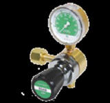 designed
for that purpose usually called station regulators. Some of these are
expensive high flow models, however there are other lower cost models which
can be used for one or two flowmeters. The one shown on the left is designed to accept up
to 200 psi inlet pressure and will hold a constant output at the preset
pressure. .
A designed
for that purpose usually called station regulators. Some of these are
expensive high flow models, however there are other lower cost models which
can be used for one or two flowmeters. The one shown on the left is designed to accept up
to 200 psi inlet pressure and will hold a constant output at the preset
pressure. .
A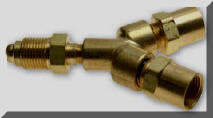 flowmeter (or a fixed orifice) can be easily added to the output fitting.
This regulator has
the capacity to handle several flowmeters. On the right is an
inexpensive adapter that makes it easy to add two flowmeters. This
system works great with our
GSS.
The
GSS.
will quickly save enough shielding gas to pay for the regulator within a few
weeks!

Email
for details and part number information:
|
|
Using Small ID Shielding Gas Pipelines
and High Pressure to Offset Pressure Drops?
We Have Two
Patents that Accomplish Pressure Control and Gas Savings While Keeping Pressure Above 25 psi to Maintain
"Automatic Flow Compensation"
These systems work with any
length gas delivery hose. One simple system is available that works
with any length existing gas delivery hose, even one 200 feet or longer!
Email for
details.
Email with the following information:
1) Location: City
and State
2) Pipeline
pressure range
3) Type of
existing flow control (flowmeter, orifice)
4) Range of gas delivery hose lengths (pipeline drops to feeders) |
| |
|
Want a detailed report
on the above test data? It
includes a table with correction factors to calculate actual from
measured flow when pipeline pressure varies over a range from 20 to 70 psi.
CLICK HERE to
Download FREE PDF Copy: |
|
Measure Pipeline
Leak Rate:
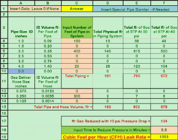 Having
problems with leaking pipeline and hoses? There is a simple way to
measure the leak rate. Use a leak down Pressure Test. The
equations needed to develop a
Spreadsheet are provided with our
"Lean Welding
Manufacturing-Shielding Gas" (part # LWM-SG) Program that makes it easy to calculate.
It is available for purchase on this web page. Having
problems with leaking pipeline and hoses? There is a simple way to
measure the leak rate. Use a leak down Pressure Test. The
equations needed to develop a
Spreadsheet are provided with our
"Lean Welding
Manufacturing-Shielding Gas" (part # LWM-SG) Program that makes it easy to calculate.
It is available for purchase on this web page. |
| |

Purchase Gas Saving Products |
Purchase Training
Aids |
|
Purchase
Flow Rate Limiter |
Purchase Wire Feeding
Aids |
|
Cable Covers & PLASMIT Torch
Protectors |
Purchase Orifice Flow Control
System |
| *Victor is a registered trademark of
Victor Technologies Corporation |


