|
 Welding
Math (and Science) Welding
Math (and Science)
For Welders, Welding
Students, Welding Instructors and Others Involved in Managing Welding
Operations.
Understanding the fundamentals of how welding, particularly MIG welding, works and will assist in producing higher quality depositis and assessing
welding problems. If you are using or planning to use MIG Robotics welding this information is essential.
|
|
See Below: Why MIG Wire
Melts
Also See: 1) Gas Pressure Versus Volume:
Below;
2) Weld Cooling Rates;
3) Effective Heat Input;
4) Calculate Weld Metal Volume;
5) Weight of
Welding Wire / Foot; 6) How to Read a Ruler;
7)
Charpy Impact Variations Explained; 8)
Teacher Testimonials About Our Welding Math and Science Information: Below |
|
Welding Math and Physics PDF
|

See "Why Gas Waste"
Video |
| Video-Welding
Math & Science-Gas Flow Control-Part 1 |
Video-Welding
Math & Science-Gas Flow Control-Part 2 |
|
Video-Welding
Math & Science-Deposition & Penetration-Part 1 |
Video-Welding
Math & Science-Deposition & Penetration-Spread Sheet Part 2 |
|
Video- Science of
MIG Welding
Shielding Gas
Flow Control |
Welder Rap- -
on Gas Video |
|
 Self
Study Program, Self
Study Program,
"Welding Math and Science;" 88 Pages, Part # WMS NOW a FREE pdf Downlod GOTO Purchase Page
This program provides basic information to help
welding students and welding supervisors understand welding process
characteristics using math and science. Includes and Appendix with
subjects like Reading a Ruler and Basic Math Functions.
CLICK to See Program Details
CLICK for Purchase Page
|
|
Received an Excellent
Question From A Recent Welding Student Who is Working as a Welding
Engineer and Watched Our, "Suggested MIG Gas Flow Settings" Video. He
Wondered How and Orifice or Needle Valve Can Automatically Set and Adjust to
the Proper Pressure to Maintain Consistent MIG Gas Flow?
The Answer is Much Longer
than the Question so a PDF was Produced:
CLICK FOR
FREE PDF OF ANSWER: |
|
MIG WELDING
What Causes MIG Welding Wire to Melt?
This is the
question I ask when giving a technical talk on the subject. Many answers
are offered. Here is what it is
NOT; the “hot arc”, radiation from the arc or the wire passing
through the arc. Two phenomena are primarily responsible for wire melting. A
simple test will explain one of them:
-
BE VERY CAREFUL, ONLY CONDUCT THIS TEST WITH INSTRUCTOR
SUPERVISION--AND STAND BACK THE WIRE MAY "EXPLODE!!" (Use a Stick welder. With the machine turned off; clamp one
end of a 3 foot length of 0.035 welding
 wire in a stick electrode holder and the other
under a work ground clamp . With the stick welder set
for 150 amps, turn it on (be careful to stand back). The wire will quickly
turn red, then white and then it will melt like a fuse. Note the short
time that took. That demonstrates one
of the causes
of wire melting during welding. As the wire
passes from the end of the torch contact tip to the arc, it is carrying all
the welding current and becomes very hot. It starts at room temperature
and can exceed 500 degrees F before the arc forms at the end (depending on the
"sickout," the distance between the tip and the workpiece.) wire in a stick electrode holder and the other
under a work ground clamp . With the stick welder set
for 150 amps, turn it on (be careful to stand back). The wire will quickly
turn red, then white and then it will melt like a fuse. Note the short
time that took. That demonstrates one
of the causes
of wire melting during welding. As the wire
passes from the end of the torch contact tip to the arc, it is carrying all
the welding current and becomes very hot. It starts at room temperature
and can exceed 500 degrees F before the arc forms at the end (depending on the
"sickout," the distance between the tip and the workpiece.)
-
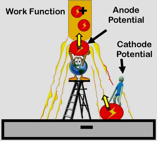
The second reason it melts is that current leaving or entering a surface, be
it wire or hot puddle, requires a given amount of energy for the electrons to enter or
leave that surface. This energy, generated at the surface, melts the already
hot wire. Therefore assuming Electrode Positive this is referred to as Anode
Potential (also called Work Function and measures as voltage) and is equal to the Amps
x Anode Voltage.
|
 The
following equation obtained from Reference (1) defines the relationship: The
following equation obtained from Reference (1) defines the relationship:
Wire
Melting Rate (lbs/hr) = a x Amps + b x Wire Stickout x Amps 2
Where "a" and "b" are constants
and "Wire Stickout" is the
distance from the torch contact tip to the workpiece measured in inches.
(Note, constant b has been modified to compensate for the fact that this
equation was based on "Electrode Extension" that is measured from the
contact tip to the top of the
arc.)
The values for "a" and "b" for
0.035 inch diameter carbon steel wire are:
a =
0.017; b = 0.00014
These two energy sources cause the wire to melt. The first term (a x Amps)
is the anode voltage times current and the second term defines the energy input
due to resistance heating.
|
|
IMPLICATION OF THE EQUATION
One
of the major implications of this relationship is that an increase in the
stickout (at a fixed wire feed speed)
amperage will decrease. That has
a significant effect on another parameter, weld penetration.
(Note,
stickout is also called tip-to-work distance. The term
"Electrode Extension" or ESO is a more accurate measure of the
distance between the end of the contact tip to the top of the
arc. However for these calculations the stickout or contact tip-to-work
can be used and is easier to measure.)
Point of
Interest
The voltage you measure on a
MIG welder is a combination of the:
-
1) Small voltage drop due to
resistive heating of the wire (I2R)
-
2) The anode and cathode
potentials (that needed to get electrons out of the wire and into the puddle;
could be 1/2 the total measured)
-
3) The voltage drop across the
resistive arc.
|
|
WELD
PENETRATION
Weld penetration can be determined by a simple equation defined some years ago
by C. E. Jackson in Reference (2)
Weld
Penetration (distance into the base material when making a weld on plate
measured in inches) =
K [Amps4
/ (Weld Travel Speed; ipm x Volts 2)]0.333
For 0.035
inch diameter solid carbon steel wire, the constant K = 0.0019
Using these equations we find the following when we change wire stickout for
0.035 inch solid wire. Assuming a fixed wire feed speed that produces 200 amps
at 3/8 inch wire stickout:
|
Stickout, inches |
Amps |
Penetration
inches |
% Loss in
Penetration |
|
3/8 |
200 |
.127 |
base |
|
1/2 |
184 |
.114 |
11% |
|
5/8 |
172 |
.104 |
18% |
|
3/4 |
162 |
.096 |
24% |
|
7/8 |
154 |
.090 |
29% |
Note:
-
With a fixed wire feed speed the amperage
decreased from 200 amps with a 3/8 inch stickout to a low of 154 amps when the stickout was increased to 7/8 inches. The resistance heating of the wire
(the 2nd Amp2 term in the equation) is a very efficient heating process.
Therefore the current needed to finish melting the wire as it enters the arc,
becomes less as the wire is hotter with longer stickout.
-
-
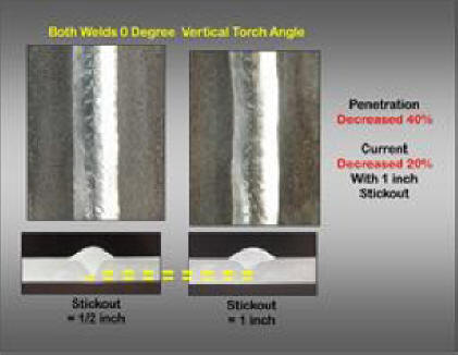
However
there is a reduction in weld penetration when varying stickout in a normal range
from 3/8 to 3/4 inches is 24%! If extended to 7/8 inches penetration
decreases 29%.
Therefore it is
very important to keep the torch stickout constant. Also the shorter the
distance from tip to work for a fixed wire feed speed the greater the
penetration since current also increases. When welding in the short
circuiting mode it is often desirable to use a long contact tip
which
protrudes from the shielding gas cup. This helps assure adequate
penetration is maintained by keeping current higher. It also helps
visibility so the welder can stay on the leading edge of the weld puddle.
The picture
right is from our recently published book and is one of several examples
presented of the effects of MIG welding parameter changes on weld performance.
See Book Details on Current
Speicals Offers Page
|
|
Weld Penetration
Definition
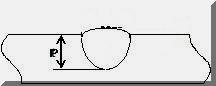
For the purposes of this exercise, weld penetration is a measure of how deep the
weld penetrates in a bead-on-plate deposit. Have a different wire than the 0.035
inch solid wire used in this example? No problem. In fact not only
changes in wire type and size but also shielding gas and torch angle will alter
the actual value. You can generate your own constant K for what you are
doing by making a bead-on-plate deposit, cutting a cross section and etching it.
|
|
Caution About the Use of This
Approach
The above equations are designed to work within a practical range for normal
MIG welding. There are much more elaborate equations that take into
account the variable resistively of material with temperature, other arc effects
etc. However within a range of normal operation the above approach will
work adequately. As mentioned, you may need to develop your own
coefficients. Make a weld, measure the depth of penetration and work
backwards! That is what Clarence Jackson did with thousands of data
points!
Reference (1): AWS Welding Handbook, Volume 1, 9th Addition; pp 79
Reference (2): “The Science of Arc Welding” by C. E. Jackson. 1960 Welding
Journal 39(4) pp 129-s thru 230-s
========== =========== ==========
|
|
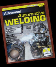 |
Book:
"Advanced Automotive Welding"
Author: Jerry Uttrachi
(President of WA Technology)
Great book for welding students to also learn some welding math and
science.
CLICK for Book Details |
 Download
PDF Overview of the Book with Contents Page and Several Pictures from Each
Chapter. Download
PDF Overview of the Book with Contents Page and Several Pictures from Each
Chapter. |
|
Review by Editors of Hemmings Motor News; August
2012
"Advanced Automotive Welding" by
Jerry Uttrachi
Welding is a hot topic in the hobby these days. For less than $500 a
do-it-yourselfer can purchase a good quality welder and start laying beads
or zapping in spot welds.
This kind of accessibility to a once specialized skill is excellent for the
hobby, and we encourage everyone with an interest to learn to weld. Just as
important as buying the gear, however, is getting versed in the many
different processes, techniques and materials used in all types of welding.
A class at a local welding school or a community college is a good place to
start, as is the purchase of a book like Advanced Automotive Welding, part
of Car Tech’s SA Design series.
Despite the “Advanced” in the title, the book is a good resource for
beginning and intermediate welders. The author, Jerry Uttrachi, is a former
American Welding Society President, with 40 years of welding experience, as
well as a car enthusiast, and he writes in a clear, mostly jargon free
style.
The book covers all welding processes, as well as cutting processes, and
includes insight into some car related welding projects. Advanced
Automotive welding is a good addition to any budding or experienced metal
worker’s shelf. |
|
========== =========== ==========
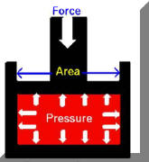
Gas Pressure/Volume Calculations
 Understanding
the relationship between gas pressure and volume will help when setting gas
flow and understanding MIG shielding gas use and waste. Understanding
the relationship between gas pressure and volume will help when setting gas
flow and understanding MIG shielding gas use and waste.
In 1662 Robert Boyle defined the basic
relationship between gas Pressure and Volume. He stated the
relationship in mathematic terms as:
P1 / P2 = V1 / V2
(Where P, pressure, is measured as absolute pressure =
gauge pressure + 14.7 psi at sea
level)
For example, in a MIG gas delivery hose if
the initial absolute pressure is doubled the gas volume must be double.
That was until 140 years later when around 1800 both Charles and Dalton
independently added temperature to the relationship! They defined the
following relationship:
V1 / V2
= T1 / T2
(Where T, Temperature is measured as absolute Temperature in degrees Rankin
= Degrees Fahrenheit gauge + 460)
Applying this equation we'll
see in general we need not worry about temperature effecting volume in
normal ranges:
i.e.
V1 / V2
=T1 / T2
If
T1=75
F than T1Rankin
=
75+460=535 R
Assume T2 = T1 +
20% =90 deg F; then T2
Rankin
= 90+460=550 R
V1/V2 due to 20
% Temp Difference =
V1 / V2
=T1 / T2=
535/550=0.97
Or
at a constant pressure, an increase in Temperature of 20% measured in
degrees Fahrenheit yields only 3% increase in volume. For most welding
purposes and over the range of production temperatures there is not enough
change in Volume with gas Temperature to
consider it significant.
The general Gas Laws can
be written as:
(P1 X V1) / T1
= (P2 x V2 ) / T2
It can also be written as P x V = (nR) T
where the constants nR can defined based on
the gas. We'll let you find details about the nR by searching
the Internet since for our purposes ratio comparisons are all we need.
MIG WELDING EXAMPLE
Assume:
-
The pressure needed in the gas delivery
hose from gas source to welder/feeder to flow 30 CFH is 3 psi.
-
A regulator/flowmeter is used that
utilizes an 80 psi regulator.
Therefore when welding stops gas
continues to flow through the needle valve flow control until the
pressure in the gas delivery hose equals 80 psi.
Then the volume of excess gas in the gas
delivery hose compared to the volume when welding will be:
V
stopped / V
welding
=
P
stopped / P
welding
=
(80
psi +15) / (3 psi + 15) = 5.3 times the physical hose
volume
Hose
Expansion Causes More Excess Volume: Tests of a standard 1/4 inch diameter gas
delivery hose showed it had a 13%
increased volume due to the hose expanding with 80 psi pressure.
Therefore 87% of the excess gas stored in the hose is
due to the increased Pressure and 13% of the excess due to Hose Expansion.
SEE MORE DETAILS.
Excess Gas
Blasts Out of the MIG
Torch When Welding Starts: The high velocity creates turbulence in
the shielding gas stream which takes several seconds to stabilize to a
desirable smooth Laminar flow. The turbulence pulls in air
causing excess
spatter and internal weld porosity. For a typical 5/8 inch diameter MIG
nozzle more than 50 CFH flow rate causes this turbulent flow. For
a smaller 1/2 inch diameter nozzle flow rates should not exceed about 40 CFH. |
|

Was This Welding Math Information Useful? What Other Math Would You Like
To See?
|
|
F REE
Technical Paper Available Entitled; "MIG Shielding Gas Control and Optimization"
(or Everything You Didn't Know You
Needed to Ask About MIG Shielding Gas Control!) It Summarizes Key points
in this Web Site and numerous Technical Presentations made in US and
International Welding Conferences about the gas
shielding problems and solutions. REE
Technical Paper Available Entitled; "MIG Shielding Gas Control and Optimization"
(or Everything You Didn't Know You
Needed to Ask About MIG Shielding Gas Control!) It Summarizes Key points
in this Web Site and numerous Technical Presentations made in US and
International Welding Conferences about the gas
shielding problems and solutions.
CLICK ICON to
Download PDF DOWNLOAD
|
|
Testimonials from Teachers About Our Welding Math
Information |
|
Email 1:
Brad Weaver,
Science Teacher
Belmont Career and Technical Education Center Sent This Email Requesting:
"..permission to use the wonderful materials you have produced on welding
math and physics with the students here at our career and technical
education center. As the science teacher at the center, I am always looking
for ways to instruct key science and math concepts and skills in the context
of the technical programs. When the lesson materials come from their field
of study, it is more meaningful to the students for the direct application
of science and math. In searching for materials on instruction regarding the
use of the ruler, I came across your website, and shared it with our welding
instructor, Mr. Greg Hutchison." We would like to incorporate your
materials into our lessons."
We Thanked Brad and Gave Permission
|
|
Email 2:
Mrs. Vicki S. Morrow, a Mathematics Teacher Asked:
“Would it be possible for me to print out and share your
welding math information with a specific student? He attends my school
part-time and a trade school the remainder of the time. I thought I could
make math more relatable to him because he is studying welding and is very
interested in the subject. I really appreciate the information available on
your site."
After providing permission she emailed and said:
"Thank you so much. Your site is perfect for what I need for my student." |
|
See YouTube Video Discussion of Our
Patented Shielding Gas Saver System
Also shows some Bernoulli gas equations
CLICK HERE OR PIC OF
OUR STREET ROD |
|

See
"Welding; Go Green" Video
CLICK Here or Picture Left
Shows Calculation
of How Industrial MIG Welders Waste 8 TONS/YEAR of CO2
(or Argon) Shielding Gas
|
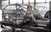
See YouTube Video Discussion of
"Welding Race Cars" with Video Clips of
Richard Petty Discussing Importance of
Welding
CLICK HERE OR PIC OF
NASCAR CHASSIS |
Calculate Weld Metal Volume for
Any Weld Joint.
Also Calculate Amount of Rod or
Wire Needed to Fill the Weld. Joint. Click
Here or ICON. |
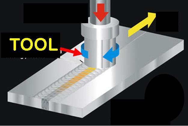
New Info-"Friction
Stir Welding" |
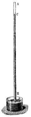  Some
additional gas physics you might find interesting was learned from a scientist,
Evangelista Torricelli, who explained the effects of a vacuum in 1643.
He solved a puzzle at the time of why irrigation and mine water pumps could
only lift water 33 feet. He also invented the Barometer (his apparatus
right.)
CHECK
IT OUT Some
additional gas physics you might find interesting was learned from a scientist,
Evangelista Torricelli, who explained the effects of a vacuum in 1643.
He solved a puzzle at the time of why irrigation and mine water pumps could
only lift water 33 feet. He also invented the Barometer (his apparatus
right.)
CHECK
IT OUT |
 Want
to know how to calculate weld cooling rate? The equations for
calculating cooling rates in thick and thin material are presented under
"Welding 4130." Cooling rates are very important to understand for
4130. However the equations can be used for any material.
CHECK IT OUT Want
to know how to calculate weld cooling rate? The equations for
calculating cooling rates in thick and thin material are presented under
"Welding 4130." Cooling rates are very important to understand for
4130. However the equations can be used for any material.
CHECK IT OUT |
Improve MIG Weld Starts
and Have Shielding Gas Cylinder Last 2 to 3 Times Longer! Click Here.
Ideal for Welding Schools
CLICK FOR DETAILS
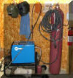
A small shop fabricator
in Georgia with a Miller TM 175 amp welder
purchased a 50 foot Gas Saver System so he could use a larger cylinder
and mount it on the wall of his shop. He wrote:
"The system works great.
Thanks for the professional
service and a great
product."
CHECK OUT HIS SHOP
|
 |
Purchase Flow Rate Limiter |
Purchase
Gas Saving
Products |
|
|
|
Purchase
Training
Products |
Purchase Wire Feeding Aids |
|
| |
|
Purchase Replaceable Orifice Flow Control System |
|


