Background Details/History:
Some references
site Robert Hopkins for having invented the Electroslag welding process in the
1930's. Most of his patents relate to Electroslag melting for ingot
manufacture, not welding. However one US patent, number 2,191481 filed in
June, 1939 does describe the surfacing of one material on another. The
illustration, however looks more like a melting
furnace than welding. In fact the fellow who invented Submerged Arc
Welding, Harry Kennedy, was
granted a US patent in October of 1950, number 2,631,344, assigned to Linde
Division of UCC that more closely related to Electroslag welding. However it too
falls short of defining what we know today as this simple welding process.
 A unique version
of the Consumable Guide
Electroslag Welding Process was developed and patented (US Patent Number
2,868,951 filed in March 1957, assigned to the Linde Division of UCC) by a colleague, Harry Shrubsall.
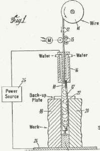
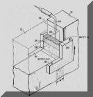
The figure on the left is from that patent. It clearly shows the
process as it is known today. Harry's patent includes the use of a flux
coated tube to replace part of the flux that plates out on the copper molds.
It also insulates the metal guide tube from the work.
A unique version
of the Consumable Guide
Electroslag Welding Process was developed and patented (US Patent Number
2,868,951 filed in March 1957, assigned to the Linde Division of UCC) by a colleague, Harry Shrubsall.
The figure on the left is from that patent. It clearly shows the
process as it is known today. Harry's patent includes the use of a flux
coated tube to replace part of the flux that plates out on the copper molds.
It also insulates the metal guide tube from the work.
The Paton Institute
in Russia introduced the process and did a great deal of development work. They published a book, "Electroslag Welding" in 1959 with an English
translation published by The American Welding Society in 1962. Of the 92
references sited in that text, most range in dates from 1955 to 1959. The
first mention of Electroslag is in a paper entitled "Electroslag Welding,"
published in Avtomaticicheskaya Svarka in 1953 by Voloshkevich.
Harry Shrubsall and I worked as engineers in the Linde
Development Labs (although I started after his invention!). Harry had
several subsequent patents on the use of the process to butt weld Railroad Rails.
Patent numbers 3,192,356 and 3,291,955 filed on September 1962 and February 1963
respectively describe Railroad Rail welding with Consumable Guide
Electroslag.
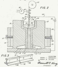 I worked on a Plate Electrode
Electroslag Welding development with Harry, It used a triangular shaped
electrode with two holes that
spread two electrodes at the bottom to weld the Rail Base
then narrowed them to weld through the Rail Web and the Rail Head on top. Welds were excellent and passed all
required Railroad tests. The resulting welds were far better quality than the Thermite deposits often employed but did
take longer to make. This extra time ultimately caused resistance to its
use. If a train happens to be coming down the track, all workers want to
be able to move fast! Can't blame them.
I worked on a Plate Electrode
Electroslag Welding development with Harry, It used a triangular shaped
electrode with two holes that
spread two electrodes at the bottom to weld the Rail Base
then narrowed them to weld through the Rail Web and the Rail Head on top. Welds were excellent and passed all
required Railroad tests. The resulting welds were far better quality than the Thermite deposits often employed but did
take longer to make. This extra time ultimately caused resistance to its
use. If a train happens to be coming down the track, all workers want to
be able to move fast! Can't blame them.
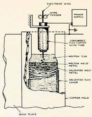
Refer to the schematic below copied from the original Linde
Publication 51-220 "Procedures for Consumable Guide Electroslag Welding." In the
Electroslag Welding process current transfers from the guide tube to the welding
wire and in turn though a molten flux bath. The resistance of the flux
bath creates the heat and temperature that melts the wire and surrounding base
material. The guide tube itself will also contact the molten flux bath
periodically which will cause an increase in welding current as the end is
consumed. The molten flux will solidify on the copper retaining molds
which are placed on the sides on the weld joint. This flux layer protects
the copper molds from having direct contact with the weld.
The Linde Flux Coated Guide Tube defined in Harry's
original patent looked like a big stick electrode! They were made with
a hole down the center and a thin flux coating that protected the tube from
shorting to the plate side walls and also automatically compensated for a
portion of the flux that plated out on the copper retaining shoes. The
tubes were purposely coated with a quantity of flux that was less than the
amount that plated out on the copper molds (see schematic on left showing flux
layer that plates out on the copper molds ) This avoided excess flux build-up in the joint as
welding progressed. Therefore additional flux was always needed and was
added by the operator but far less frequently than when uncoated tubes were
used. ( The concept of adding
flux by listening to the sound, works great in a Laboratory environment.
However in a noisy shop it is not effective. There are
some simple tricks at measuring flux depth.) For multiple tube welding of heavy sections (up to 4 tubes for
8 inch thick plates) a special very thinly flux coated tube (referred to as Type
M) was used so as not
to produce excess flux burden as welding progressed up the joint. Special
slip-on metal guide tube clips centered the tubes and prevented vibration and
shorting. This was possible since the tubes flux coating was an insulator.
Little preparation was needed to center the tubes. Those fabricators that
employed bare tubes could have shorting problems that caused equipment failures
and the worse thing that can happen during an Electroslag weld - - having to
restart!
Linde's patented Flux Coated Guide Tube Process was very successful for the user since a great
deal of welding time and plate preparation were saved. It was also very
successful for Linde who obtained a substantial patent royalty (>
$1/foot of tube) built into the sale of the Flux Coated Guide Tubes. They
were used extensively with some
the notable applications being:
1. Over 1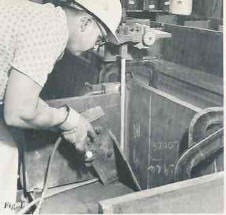 00,000 feet of Flux Coated Consumable Guide Tubes
were used by Kaiser Steel to
weld massive columns for the Bank of America Headquarters in San Francisco.
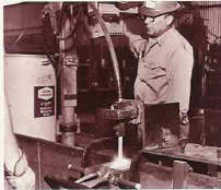
This process was very successful and made some difficult to do any other way,
transitions joints. Thin coated tubes were used in locations where there
were only captive steel weld dams. The operator at left is placing a copper dam
on a box beam reinforcing plate. Four Electroslag welds will
secure the plate to the heavy wall box beam. An article entitled
"Electroslag Welding with Consumable Guide on
00,000 feet of Flux Coated Consumable Guide Tubes
were used by Kaiser Steel to
weld massive columns for the Bank of America Headquarters in San Francisco.
This process was very successful and made some difficult to do any other way,
transitions joints. Thin coated tubes were used in locations where there
were only captive steel weld dams. The operator at left is placing a copper dam
on a box beam reinforcing plate. Four Electroslag welds will
secure the plate to the heavy wall box beam. An article entitled
"Electroslag Welding with Consumable Guide on
 the Bank of America World
Headquarters Building," published in The Welding Journal in 1968 by
Tommy Agic of Kaiser Steel and Jim Hampton of Linde, mention that a total of
23,000 welds were made for the job. Plate thickness ranged from 1/2 to 5
inches. The massive columns ranged from 26 to 42 feet long. The
operator on the right is making a beam splice joint with the consumable guide
Electroslag process.
the Bank of America World
Headquarters Building," published in The Welding Journal in 1968 by
Tommy Agic of Kaiser Steel and Jim Hampton of Linde, mention that a total of
23,000 welds were made for the job. Plate thickness ranged from 1/2 to 5
inches. The massive columns ranged from 26 to 42 feet long. The
operator on the right is making a beam splice joint with the consumable guide
Electroslag process.
2.
Thousands of feet of Electroslag welds made on the John Hancock
building in Chicago:
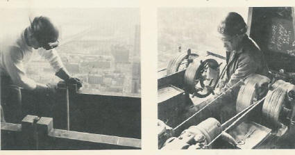
(Above
photos
from a Linde publication F-51-220. On right are two simultaneous welds being made on
beam flanges splices on the edge of the John Hancock building under construction. Each
weld is being made with two Linde Flux Coated Guide Tubes. The photo on
the left shows the weld joint being prepared)
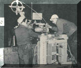
3.
12 foot long seams made in 1 ½ to 2 inch steel for the 72 cubic
yard bucket for Texas Gulf Sulfur dragline. A standard sub arc tractor was
used to make these welds with the simple addition of a guide tube holder, see below:
When welded with manual stick electrodes these 12
foot seams required 150 pounds of electrodes and 40 man hours to complete.
With Consumable Guide Electroslag the electrode requirements reduced to 40
pounds and the weld was completed in 1 3/4 hours.
4.
Detailed application information was described in a Welding
Journal Article entitled “Vertical Submerged Arc Welding,” by Paul Masters from
American Bridge Division of US Steel and Bob Zuchowski from Linde (Linde
Publication 52-539).
5. In addition to the high speed conventional Electroslag used at
National Shipbuilding in San Diego (mentioned above), they also made many
hundreds of welds splicing deck stiffeners on Roll-On-Roll-Off ships with Flux
Coated Consumable Guide Tubes. The process was also used for other
applications and other shipyards.
The royalty income derived from the sale of the Patented
Guide Tubes allowed my Welding Process R & D Group to develop numerous applications and
procedures for the Consumable Guide Electroslag Welding Process. At one time we
had 7 engineers/technicians working on the process in our Laboratory. After successfully welding
steel anode bars in an aluminum pot line (with the line in operation) and a market evaluation, we
decided to do extensive research on the welding of massive aluminum busbars used
in aluminum production.
Other companies also introduced Electroslag systems in the
US. Arcos marketed both conventional Electroslag and Consumable Guide
Electroslag products. They produced a plate electrode, some of which were dip coated with
flux as I recall. Arcos also marketed products for an Electrogas process. The Electrogas process utilized a cored wire with flux added to replace that which coated the weld retaining copper shoes.
Hobart developed a simple oscillator which allowed the
welding of heavier plate without the need for additional guide tubes and related
equipment.
Airco marketed an Electrogas process which used a
solid wire and argon based gas mixture. In was used by the Litton Shipyard
in Erie Pennsylvania to make the vertical hull welds in ship tankers.
Lincoln introduced a vertical welding process which used a self shielded flux cored
wire and operated with moving shoes.


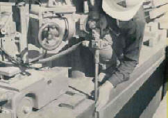
 Welding
equipment for Consumable Guide Electroslag can be made from Heavy Duty MIG
feeders (today's digital designs allow precise control) or existing Sub Arc
equipment can be used by inserting the guide tube into a specially modified
busbar. See Accompanying photo. A design for a guide tube holder can be
provided. Simple power source recommendations avoid expensive equipment
purchase.
Welding
equipment for Consumable Guide Electroslag can be made from Heavy Duty MIG
feeders (today's digital designs allow precise control) or existing Sub Arc
equipment can be used by inserting the guide tube into a specially modified
busbar. See Accompanying photo. A design for a guide tube holder can be
provided. Simple power source recommendations avoid expensive equipment
purchase. he
Consumable Guide Aluminum Electroslag Welding process was developed in our Laboratory and produced welds in 2 inch think (50 mm) and 4
inch thick (100 mm) busbar material. Welds were made at a very rapid rate of vertical travel speed not
possible with steel welding. A sample of a weld made with the process is
shown on the left. Unfortunately the main application for the process was for
joining heavy aluminum busbars. These are mostly employed in aluminum
production facilities and the market for aluminum had significantly deteriorated.
The development work was therefore terminated and the process was not commercialized.
he
Consumable Guide Aluminum Electroslag Welding process was developed in our Laboratory and produced welds in 2 inch think (50 mm) and 4
inch thick (100 mm) busbar material. Welds were made at a very rapid rate of vertical travel speed not
possible with steel welding. A sample of a weld made with the process is
shown on the left. Unfortunately the main application for the process was for
joining heavy aluminum busbars. These are mostly employed in aluminum
production facilities and the market for aluminum had significantly deteriorated.
The development work was therefore terminated and the process was not commercialized.

 We
developed a "High Speed Electroslag Process" that
We
developed a "High Speed Electroslag Process" that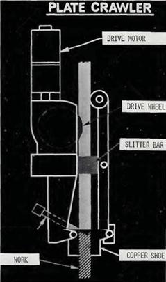 was used
in production by a
number of companies. We were granted a US patent (# 3,854,028) on the
process. It
utilized a unique Metal Cored Wire that was a low carbon, high Mn, Si alloy but
had an oxygen content of from 500 to 1000ppm versus the low oxygen we were
usually working to achieve! The figure on the left is from the patent.
The wire was also patented (US Patent # 3,778,587.) An article
entitled "Electroslag Welding Speeds the Welding of Ships" was published in
the American Welding Society's Welding Journal (April, 1974) defining the procedures and application at what was
then named
was used
in production by a
number of companies. We were granted a US patent (# 3,854,028) on the
process. It
utilized a unique Metal Cored Wire that was a low carbon, high Mn, Si alloy but
had an oxygen content of from 500 to 1000ppm versus the low oxygen we were
usually working to achieve! The figure on the left is from the patent.
The wire was also patented (US Patent # 3,778,587.) An article
entitled "Electroslag Welding Speeds the Welding of Ships" was published in
the American Welding Society's Welding Journal (April, 1974) defining the procedures and application at what was
then named
 National Steel And Shipbuilding in San Diego California.
The authors were Ray Parrot (Welding Engineer at the yard), Sid Ward
(Manager of Engineering, West Coast Region of Linde) and myself, Jerry Uttrachi.
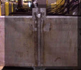
A schematic of the moving device is shown on the upper right. The
picture on the left from the AWS Journal article and shows the Plate Crawler
as it was called mounted on a ship hull butt seam.
National Steel And Shipbuilding in San Diego California.
The authors were Ray Parrot (Welding Engineer at the yard), Sid Ward
(Manager of Engineering, West Coast Region of Linde) and myself, Jerry Uttrachi.
A schematic of the moving device is shown on the upper right. The
picture on the left from the AWS Journal article and shows the Plate Crawler
as it was called mounted on a ship hull butt seam.