Example
High Gas Flow With MIG Welding Causing Erratic Arc, Some Might Call Arc Blow
An interesting situation shows what can happen if excess shielding gas flow is
used. An experienced field
Welding Engineer was testing a new model multiprocess power source in a fabricators
shop. It worked fine in the Stick and TIG mode. However when he switched
to MIG welding with a cylinder of 75% Argon 25% CO2 gas the arc was
harsh, erratic and the spatter was very high with poor weld surface
appearance. After checking grounding, polarity and
making settings changes with no improvement he called the power supply manufactures Product Manager. After
discussing the problem, the Product Manager wondered about the gas flow rate
and asked to have it checked. The field Welding Engineer said it was set for
30 (he assumed CFH.) The Product
Manager had experience with poor performance when flow rates were set
excessively high. He asked the field Welding Engineer to put the MIG
gun
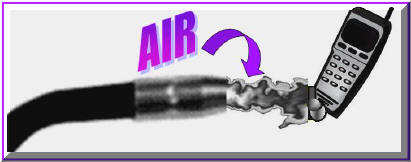
nozzle up to his cell phone and pull the trigger with the wire disconnected! The solution was
evident from the sound this very experienced Product Manager heard - the
flow was excessive! Sure enough, the distributor salesman who set-up
the installation had used a standard inert gas regulator. It was not a
Regulator/Flowgauge with an outlet orifice and flow calibrated pressure
gauge. It was reading 30 psi not 30 CFH! What flow were they
getting? No doubt over 150 CFH.
interesting situation shows what can happen if excess shielding gas flow is
used. An experienced field
Welding Engineer was testing a new model multiprocess power source in a fabricators
shop. It worked fine in the Stick and TIG mode. However when he switched
to MIG welding with a cylinder of 75% Argon 25% CO2 gas the arc was
harsh, erratic and the spatter was very high with poor weld surface
appearance. After checking grounding, polarity and
making settings changes with no improvement he called the power supply manufactures Product Manager. After
discussing the problem, the Product Manager wondered about the gas flow rate
and asked to have it checked. The field Welding Engineer said it was set for
30 (he assumed CFH.) The Product
Manager had experience with poor performance when flow rates were set
excessively high. He asked the field Welding Engineer to put the MIG
gun
nozzle up to his cell phone and pull the trigger with the wire disconnected! The solution was
evident from the sound this very experienced Product Manager heard - the
flow was excessive! Sure enough, the distributor salesman who set-up
the installation had used a standard inert gas regulator. It was not a
Regulator/Flowgauge with an outlet orifice and flow calibrated pressure
gauge. It was reading 30 psi not 30 CFH! What flow were they
getting? No doubt over 150 CFH.
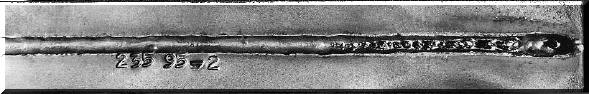
 Even
with a 5/8 inch MIG gun nozzle, much more than about 50 to 60 CFH will cause
turbulent flow and mix air into the shielding gas stream! It takes
only a small amount of air to produce a less stable arc with excess
spatter and internal weld porosity-if it is not visible! Very high flows, as
in this situation, can cause to arc to "Blow" sideways or erratically.
Perhaps more harmful than the visible defects is the effect of Nitrogen on
the weld deposit.
Even
with a 5/8 inch MIG gun nozzle, much more than about 50 to 60 CFH will cause
turbulent flow and mix air into the shielding gas stream! It takes
only a small amount of air to produce a less stable arc with excess
spatter and internal weld porosity-if it is not visible! Very high flows, as
in this situation, can cause to arc to "Blow" sideways or erratically.
Perhaps more harmful than the visible defects is the effect of Nitrogen on
the weld deposit.
Note: In the above example, when the proper
regulator/flowgauge was installed, MIG weld performance was fine!
See What That
Can Cause.


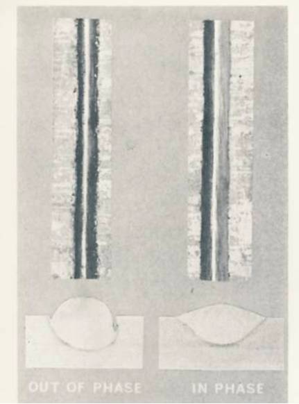 Multiwire SAW has a significant arc interaction, which could be considered an Arc Blow problem if when using AC power the system is not phased properly. The photo left was made with a three-wire system operating at high speed and the only difference in the welds was the power phasing. All parameters other than phasing were identical! The research done to define the proper system and increase welding speeds for making large diameter gas and oil pipe is discussed in a free PDF download.