|
|
|
HISTORY OF MIG (GMAW) WELDING
continued-- Page 3
TANDEM MIG
|
|
 I
was somewhat surprised when searching the patent record to find two patents from
friends on a process I did not realize was even contemplated at that time
period, Two Wire MIG! I
was somewhat surprised when searching the patent record to find two patents from
friends on a process I did not realize was even contemplated at that time
period, Two Wire MIG!
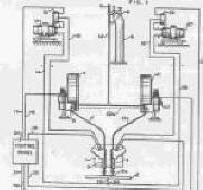
The first, Patent Number 2,906,861 was filed in September
1957 by Lesnewich, assigned to Airco (figure upper left). This was truly a
Multipower-Multiwire system using two torches and two DC power sources.
Variations are covered including the use of AC power. The company
Lesnewich worked for, Airco, produced an emissive coated MIG wire which ran on
AC. It was difficult to keep the coating consistent and it was not
commercially successful.
|
|
The second system was patented by a fellow who I worked
with for many years,
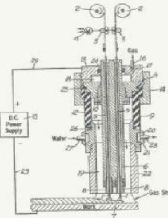 JJim Newman.
Jim had also worked with Clarence Jackson in
the days of Submerged Arc welding process development. It was Patent Number
3,007,033 filed in April, 1959, assigned to Linde. The claims are centered
around welding aluminum and magnesium. The process, unlike that defined by Lesnewich, used two electrodes connected
electrically in parallel. Therefore amps and volts would be the same for each
electrode, assuming they were the same diameter (see figure upper right). JJim Newman.
Jim had also worked with Clarence Jackson in
the days of Submerged Arc welding process development. It was Patent Number
3,007,033 filed in April, 1959, assigned to Linde. The claims are centered
around welding aluminum and magnesium. The process, unlike that defined by Lesnewich, used two electrodes connected
electrically in parallel. Therefore amps and volts would be the same for each
electrode, assuming they were the same diameter (see figure upper right).
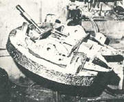
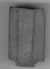 Some innovative MIG techniques were developed in the early days of the
process development. Some were very creative. One was the narrow
gap MIG weld (photo left) was made at 25 lbs per hour deposition rate in a
1/2 inch straight side wall gap. This weld sample was sufficiently
innovative that I have kept it along with only a few others over the
approximately 40 years since it was made! The economics and tracking
systems at the time made some of these processes not as attractive as they
would be today. Click to see a
proposal regarding a Report on this development. Some innovative MIG techniques were developed in the early days of the
process development. Some were very creative. One was the narrow
gap MIG weld (photo left) was made at 25 lbs per hour deposition rate in a
1/2 inch straight side wall gap. This weld sample was sufficiently
innovative that I have kept it along with only a few others over the
approximately 40 years since it was made! The economics and tracking
systems at the time made some of these processes not as attractive as they
would be today. Click to see a
proposal regarding a Report on this development.
|
|
PULSE ARC
WELDING
 One
of the next major MIG innovations was Pulse Arc welding. Short Arc was
fine for sheet metal and thinner materials. However on thicker sections it
was more difficult to assure adequate penetration. Some folks knew how to
control the process and train welders. J. Ray McDermott in Louisiana was a
case in point for doing it right. They built heavy section off shore drill
rigs almost exclusively with Short Arc with excellent results. One
of the next major MIG innovations was Pulse Arc welding. Short Arc was
fine for sheet metal and thinner materials. However on thicker sections it
was more difficult to assure adequate penetration. Some folks knew how to
control the process and train welders. J. Ray McDermott in Louisiana was a
case in point for doing it right. They built heavy section off shore drill
rigs almost exclusively with Short Arc with excellent results.
However Pulse Arc welding gave added assurance the welds
would be free from "cold laps" (lack of penetration.) Needham from The
British Research Association filed a patent, Number 3,249,735, assigned to them
on July 1963 which defined the process. As he states; " The basic principle
is the arc shall work cyclically on at least two cyclically reoccurring
levels..."
In October 1968, Anderson filed patent 3,588,465 assigned
to Airco that defined a line voltage compensated Pulsed Arc power supply.
In January 1969, Daggett filed a patent number 3,588,466 also assigned to Airco
for a Pulsed Arc power supply with a background level to help stabilize the
process. These first Pulsed Arc systems were not easy to set-up but did
provide excellent all position results on heavy plate as well as on materials
such as aluminum and bronze. In fact the first model, called the PA-1, was
so difficult to set, when I saw one in the fabrication shop at Sun Ship in
Philadelphia, I asked the welding engineer if they had evaluated it for welding
heavy steel plates. He said, "No way, it is set for repairing bronze
propellers and if anyone changes those settings I'll break their arm."
One could only select from a few pulse frequencies and setting the background
and peak current was much more hit or miss than science.
A variant of the Pulsed Arc system was a much similar
process, albeit not as flexible, called Ripple Arc. Manz was awarded a
patent, number 3,524,041 assigned to Linde, for that system having filed in
September 1966.
|
|
HI DEPOSITION MIG WELDING
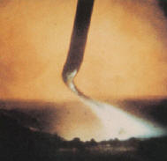 Lesnewich
in a paper published in the Welding Journal in 1958 (reference 1) described a
unique mode of metal transfer-Rotary Spray. The phenomena occurs at high
currents on small diameter wires. If controlled, it produces very high
deposition rates. See photo of a Rotary Spray Arc on the left. The
wire is tapering due to the electrical pinch forces. As it tapers the
magnetic fields cause the end of the wire to rotate rapidly. Lesnewich
in a paper published in the Welding Journal in 1958 (reference 1) described a
unique mode of metal transfer-Rotary Spray. The phenomena occurs at high
currents on small diameter wires. If controlled, it produces very high
deposition rates. See photo of a Rotary Spray Arc on the left. The
wire is tapering due to the electrical pinch forces. As it tapers the
magnetic fields cause the end of the wire to rotate rapidly.
Lyttle in an AWS paper published in the Welding
 Journal in 1983 (reference
2) described a practical use of the Rotary Spray Arc process on welding "Fifth Wheels." The
fabricator was welding at 20 lbs/hr with 0.035 inch diameter solid wire! The
process was developed by a Linde Division of UCC Field Representative who was very creative and
willing to spend the time to train welders on its use. It was referred to
as the Hi-Dep process. Journal in 1983 (reference
2) described a practical use of the Rotary Spray Arc process on welding "Fifth Wheels." The
fabricator was welding at 20 lbs/hr with 0.035 inch diameter solid wire! The
process was developed by a Linde Division of UCC Field Representative who was very creative and
willing to spend the time to train welders on its use. It was referred to
as the Hi-Dep process.
The photo on the right is the "5th Wheel" application
which consisted of making 3/8 inch and larger fillet welds. The basic
problem with this mode of Spray transfer is that it becomes stable at only high metal
deposition rates. The transition from the normal Spray transfer mode to Rotational
Spray is a rather wide unstable range.
Church in a patent filed in August 1982 (Patent Number 4,463,243)
introduced what he called the T.I.M.E. process. It had a number of
elements but produced high deposition rates with solid MIG wires without the need to have Rotational
Spray. His success however was much like that of the Linde Field Sales
Representative. When there was extensive ongoing welder training they
process could be used successfully.
|
Similar
to the deposition rate range of the T.I.M.E. process, a patent by DeVito, et al
(I was one of the et al's!)
assigned to Linde Division of UCC described a similar process. Patent
number 4,645,903 filed in July 1984, describes how the process works.
It used a conventional water cooled MIG Gun with a recessed tip and long cup to
achieve increased wire extension. It also used a special gas mixture
which allowed it to operate below Rotational Spray mode while maintaining a
stable arc. The process operated between normal Spray Arc and the
Rotary-Spray defined by Lesnewich, above. The minimum current and wire
feed speed for Rotary Spray was much higher than many welders could
handle successfully. |
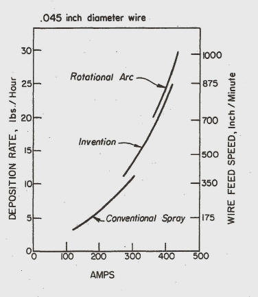
The graph on the right is from the patent and shows deposition rates with
0.045 inch diameter wire. This intermediate deposition process could be
controlled over a much wider wire feed speed and welding current range.
The process variant can operate with wire deposit rates into the "very high
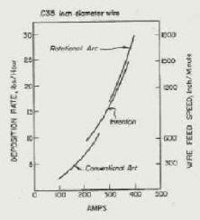
deposition rate mode" as well. The figure in the upper left shows the
deposition rate curves for 0.035 wire. The wire feed speeds are more
practical for 0.045 inch diameter wire although feeding at 700 ipm is not
easy. A special high speed wire feed motor was needed for 0.035 inch
diameter wire which required 1200 ipm wire feed speed to achieve 20
pounds per hour. The advantage is only 340 amps was needed to achieve
20 pounds per hour where 0.045 requires 400 amps. Spray arc welding at 400
amps is very hot! You need special MIG guns and a product called "Cool
Hand Luke" to make this a usable process. However achieving 20 lbs/hr
deposition rate (or more) with solid wire is a very productive, economical
method for some applications.
Want to know more about the
process?
|
|
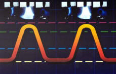
Demand Pulse
Many innovations came from
individuals or smaller companies. A patent b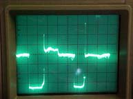 y
Hoyt, et al filed June 16, 1983 (Patent Number 4,523,077) took
advantage of then state of the art fast switching power components,
MOSFET's, and designed and marketed a successful power source that performed
like "Short Arc" but without or with very few shorts. This eliminated
the spatter that accompanies the short circuiting MIG. The process has
lower peak currents than Pulse MIG (100 to 400 amps depending on setting)
and they last for a little as 3 milliseconds. Oscilloscope photo of
the process in operation, right. The patent was assigned to Big Four
Manufacturing Company. y
Hoyt, et al filed June 16, 1983 (Patent Number 4,523,077) took
advantage of then state of the art fast switching power components,
MOSFET's, and designed and marketed a successful power source that performed
like "Short Arc" but without or with very few shorts. This eliminated
the spatter that accompanies the short circuiting MIG. The process has
lower peak currents than Pulse MIG (100 to 400 amps depending on setting)
and they last for a little as 3 milliseconds. Oscilloscope photo of
the process in operation, right. The patent was assigned to Big Four
Manufacturing Company.
|
Page
 1
2 3
(4 last) 1
2 3
(4 last)
Have a Welder?
Improve Weld Starts and Have Shielding Gas Cylinder Last at Least Twice as
Long!
Note: Our Patented
GSS
is Not Available in "Stores"
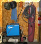
A home shop fabricator
in Georgia with a Miller TM 175 amp welder
purchased a 50 foot Gas Saver System ( GSSTM
) so he could use a larger cylinder
and mount it on the wall of his shop. He wrote:
"The system works great.
Thanks for the professional service and
a great product."
Click To See His Home Shop
A Professional
Street Rod Builder Had This to Say:
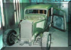 With their standard MIG welder gas delivery hose the peak shielding flow at
weld start was measured at 150 CFH. That caused air to be sucked into the
gas stream causing poor weld starts. With the
GSS replacing their existing hose, the peak flow surge at the
weld start was about 50 CFH. Total gas use was cut in half. With their standard MIG welder gas delivery hose the peak shielding flow at
weld start was measured at 150 CFH. That caused air to be sucked into the
gas stream causing poor weld starts. With the
GSS replacing their existing hose, the peak flow surge at the
weld start was about 50 CFH. Total gas use was cut in half.
Kyle Bond, President, quickly saw the improvement achieved in weld start
quality as a significant advantage! Kyle, an excellent automotive painter,
was well aware of the effects of gas surge caused by pressure buildup in the
delivery hose when stopped. He has to deal with the visible effects in the
air hose lines on the spray gun in his paint booth! The paint surge is
visible and creates defects unless the gun is triggered off the part being
painted! We can’t do that with our MIG gun!
GAS SAVER SYSTEM (GSS TM)
PURCHASE INFORMATION
|
|
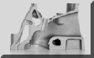
MIG Gas Delivery and the Small Block Chevy Evolved in a Similar
Way and Time!
Both had Advances and
Setbacks Before
They Were Optimized!
Click
for a PDF Report on the Similarities |

Free Technical Paper, "MIG
SHIELDING GAS
CONTROL"
CLICK ICON for PDF DOWNLOAD |
|
"WARNING:
"Weld
Safely" |
 |
▲HOME
►CONSULTING
SERVICES
|


