|
HISTORY OF SUBMERGED ARC WELDING
continued-- Page 4
THE WAR
YEARS
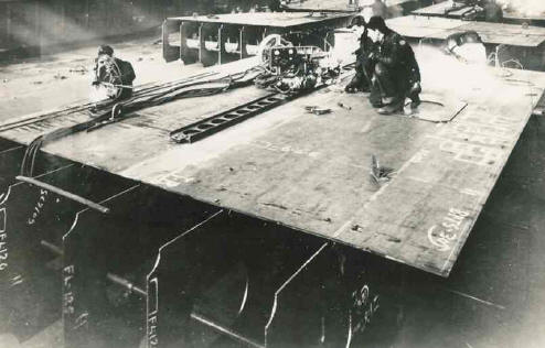
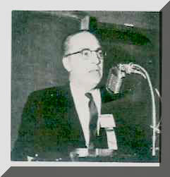
Little information was published during the War years. No
doubt some of this is due to security. The picture and comments below it are
typical of what the Submerged Arc process was able to accomplish in
shipbuilding.
|
|
In a June 1999 Welding Journal article entitled,
“Welding's Vital Part
in Major American Historical Events” written by Bob Irving, he quotes an
interesting anecdote about the Submerged Arc process:
“The importance of welding was emphasized early in the war when President
Roosevelt sent a letter to Prime Minister Winston Churchill, who is said to have
read it aloud to the members of Britain's House of Commons. The letter read in
part, "Here there had been developed a welding technique which enables us to
construct standard merchant ships with a speed unequaled in the history of
merchant shipping."
The technique the President was referring to was undoubtedly Submerged Arc
welding, which was capable of joining steel plate as much as 20 times faster
than any other welding process at that time. “
An interesting statistic is presented in a 200 page 1947 report prepared by
the US Surgeon Generals Office evaluating WW II shipyard welders health issues
(Reference 15.) They examined over 3000 welders. They provided some
statistics regarding welding methods. It was stated that a Liberty Ship
required 37.5 miles of welds. Stick welding was employed for 30 miles
and 7.5 miles (20%) was made with submerged arc welding (which they referred to
as Unionmelt, the Linde Divisions Trade Name for the process.) Although not a direct correlation to the Liberty Ship
statistic, they also defined the percentage of welders who performed arc
welding versus as they stated "Unionmelt" welding in shipyards. Stick welders
constituted 80% while Unionmelt welders were listed at 6.2%.
The discrepancy between the footage of welds made (20%) and the number of welders
(6.2%) is understandable. Unionmelt (submerged arc) welds were often very
heavy and used for butt welding deck plates, hull plates in shop, etc.
It was common to weld at very high currents. One fused flux widely used in WW
II, Unionmelt Grade 20, employed a manufacturing QA test using straight length 3/8 inch diameter rods welding
at 2000 amps! (Of note, that Grade 20 flux production QA test was
employed though the early 2000's! It was interesting to see the hole in
the QA Lab where the 3/8 inch rod protruded through the ceiling!) Weld
deposition rate was 4 to 5 times higher
than stick welding. Its likely the 7.5 miles of submerged arc
welds were at least twice as heavy as stick welds. It would not be
surprising if the amount of deposited weld metal with submerged arc was about 30% of
the total deposited in a ship. One of the few remaining uses of heavy welding is Diesel
Electric traction motor cases where 2 inch thick material is welded with two
passes, one from each side. That weld is made with a single electrode
operating at about 1500 amps.
An interesting anecdote relates to a discussion with a shipyard welding
engineer in the late 1960's. He was working at Sun Ship in Philadelphia
Pennsylvania and had worked there during WW II. I asked why they were not
using submerged arc welding to weld deck plates when it was widely used in WW
II. He said; "During WW II when we asked the fitting crew to fit the
deck plates so you could not fit a business card in the gap, it was done.
Today if I ask for that to be done they would laugh!" Shows the "will do"
attitude during that war time environment. He also said; "The
shipyard management periodically swapped the welding supervision with the
fitting supervision. The fitting crews soon learned what poor fit-up meant
to the welders!"
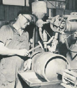
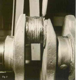
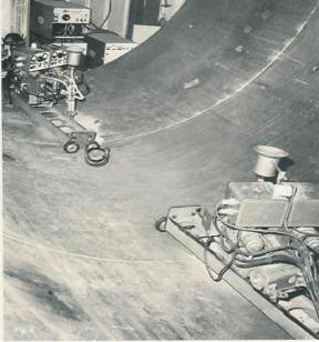
EXAMPLES
OF THE PROCESS APPLICATION
The process was used by many industries so it would be
unrealistic to try to list them all. These few pictures provide a view of some
early applications:
|
 |
 |
|
|
THE
SCIENCE OF ARC WELDING
An
old friend and colleague Clarence Jackson was Associate Manager of the Linde
Laboratories when I joined. He was an expert in Submerged Arc welding, the
Department where I worked. He was a wealth of knowledge about the technical
aspects and science of Submerged Arc welding. Since unlike the other
young engineers in the Laboratory
who all worked in the MIG/TIG (GMAW/GTAW) Department I could not see the arc and
weld puddle! Clarence and an oscilloscope were my “eyes” into what was occurring under all that
“powder!” Clarence was AWS President 1963-64. He then went to
Ohio Sate where he was a Professor in the Welding Department. Clarence remained
a good friend and every year I provided his laboratory with fluxes, flux raw
materials etc.
Clarence presented the American Welding Societies Adams
Lecture in 1959. Entitled The Science of Arc Welding it is a wealth of
information and a summary of the science of the time. I urge all students of
welding to read this 30 page document, published in the Welding Journal (See
Below). There
are 80 references listed and equations presented not only for Submerged Arc but
for other arc processes as well. Note, a compolation of these three published papers was produced by his employer at the time, the Linde Division of UCC. We have made copy of this archive Linde publication available Free of Charge, with the purchase of several training programs as well as with our recently published "Advanced Automotive Welding" book, SEE Training under the "Buy Tab" on top of page.
When you review Clarence’s technical work such as his work
on Submerged Arc Weld penetration you are overwhelmed by the number of
laboratory tests conducted. A fellow who worked with me for many years,
Jim
Newman, had worked for Clarence and would discuss the many months spent making
welds in an Edisonian fashion to assure all parameters were evaluated.
In the Closure statement in his Adams Lecture he states his
philosophy of research: “Engineering knowledge starts with the accumulation of
empirical data, which to begin with, can only be qualitative. As new approaches
are used, and especially when new methods of measurement and techniques for
studying the phenomena become available, these qualitative data gradually
develop into quantitative data which serve as a basis for the theoretical
analysis of the phenomena which we are studying.”
When you review his published work you’ll agree he was very
through and developed simple to understand and easy to use models and methods.
All of the 80 references in that publication but suggest for those interested in
understanding what is occurring under the Submerged Arc flux read the following
Jackson published papers:
- C. E Jackson, "The Science of Arc Welding," The Welding
Journal, (39) (Three Parts) 129-s to 140-s;177-s to 190-s; and 225-s to 230-s
- C. E. Jackson and A. E. Shrubsall, “Energy Distribution
in Electric Welding,” The Welding Journal, 29 (10) Research Supplement 520-a
to 521a (1959).
- C. E. Jackson and A. E. Shrubsall, “Control of
Penetration and Melting Ratio with Welding Technique,” The Welding Journal, 32
(4) Research Supplement 172-s to 178-s (1953).
- "The Effect of I2RHeating on Electrode
Melting Rate," by Wilson, Claussen and Jackson, The Welding Journal, 1956,
35(1), pp 1-s
|
|
Page
 1
2
3
4
5(last) 1
2
3
4
5(last)
Have a Welder?
Improve Weld Starts and Have Shielding Gas Cylinder Last at Least Twice as
Long!
Note: Our Patented
GSS
is Not Available in "Stores"
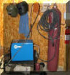
A home shop fabricator
in Georgia with a Miller TM 175 amp welder
purchased a 50 foot Gas Saver System ( GSSTM
) so he could use a larger cylinder
and mount it on the wall of his shop. He wrote:
"The system works great.
Thanks for the professional service and
a great product."
Click To See His Home Shop
A Professional
Street Rod Builder Had This to Say:
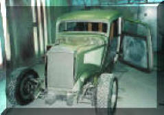 With their standard MIG welder gas delivery hose the peak shielding flow at
weld start was measured at 150 CFH. That caused air to be sucked into the
gas stream causing poor weld starts. With the
GSS replacing their existing hose, the peak flow surge at the
weld start was about 50 CFH. Total gas use was cut in half. With their standard MIG welder gas delivery hose the peak shielding flow at
weld start was measured at 150 CFH. That caused air to be sucked into the
gas stream causing poor weld starts. With the
GSS replacing their existing hose, the peak flow surge at the
weld start was about 50 CFH. Total gas use was cut in half.
Kyle Bond, President, quickly saw the improvement achieved in weld start
quality as a significant advantage! Kyle, an excellent automotive painter,
was well aware of the effects of gas surge caused by pressure buildup in the
delivery hose when stopped. He has to deal with the visible effects in the
air hose lines on the spray gun in his paint booth! The paint surge is
visible and creates defects unless the gun is triggered off the part being
painted! We can’t do that with our MIG gun!

See Video Showing
What Users Say About Our Gas Saver System-CLICK Here or Picture
|
▲HOME
►CONSULTING
SERVICES
|


