|
History of TIG (GTAW) Welding
Invention and
Development |
|
Meredith
Invents TIG:
Like MIG
welding, there are a number of references sighting "inventors” of TIG
welding.
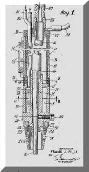
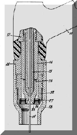
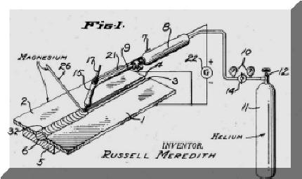 However Russell Meredith, working for Northrop Aircraft, was the
first to produce a system that was a true production tool applying for a patent in
January 1941 (US Patent # 2,274,631, Figure 1 left.) He was concerned
about meeting a critical national need of welding light weight aircraft
materials. In the first line of the patent it states; “My invention
relates to welding magnesium and its alloys - - so relatively low
melting point materials may be efficiently
welded by an electric arc.” He goes on to say that airplanes are
being made of lighter materials and a more efficient method of joining these
materials is needed. However Russell Meredith, working for Northrop Aircraft, was the
first to produce a system that was a true production tool applying for a patent in
January 1941 (US Patent # 2,274,631, Figure 1 left.) He was concerned
about meeting a critical national need of welding light weight aircraft
materials. In the first line of the patent it states; “My invention
relates to welding magnesium and its alloys - - so relatively low
melting point materials may be efficiently
welded by an electric arc.” He goes on to say that airplanes are
being made of lighter materials and a more efficient method of joining these
materials is needed. |
|
 Although
Meredith's work was done with Helium shielding gas and a tungsten
electrode his 4 patent
claims
are very broad only mentioning an "inert gas" and “refractory” welding
electrode. Validating that
this was the first workable system and
Meredith was the inventor of TIG; there is no prior art
sited against his patent by himself or the US Patent Office. Although
Meredith's work was done with Helium shielding gas and a tungsten
electrode his 4 patent
claims
are very broad only mentioning an "inert gas" and “refractory” welding
electrode. Validating that
this was the first workable system and
Meredith was the inventor of TIG; there is no prior art
sited against his patent by himself or the US Patent Office.
Similar to
the
1st
MIG Welding Patent emphasizing the need for Laminar shielding gas flow, Meredith states that the shape of the end of his TIG torch
is designed to prevent oxygen (referring to air intrusion) from being drawn into
the arc by the Helium outflow. From a review of other devices shown in
prior patents it is obvious the inventors did not understand the importance
of shielding quality and what was required to produce Laminar flow.
 Note:
I encourage reviewing these patents, which is a reason the numbers are
provided. There is a great deal of useful information available - and
they are Free!
(Unfortunately some of today's welding professionals
do not understand that excess gas flow creates
turbulence that pulls air into the shielding stream. Depending the nozzle
size, the flow rate causing turbulence is only somewhat higher than that
used when welding! ) Note:
I encourage reviewing these patents, which is a reason the numbers are
provided. There is a great deal of useful information available - and
they are Free!
(Unfortunately some of today's welding professionals
do not understand that excess gas flow creates
turbulence that pulls air into the shielding stream. Depending the nozzle
size, the flow rate causing turbulence is only somewhat higher than that
used when welding! ) |
|
Linde Buys Patents and Heliarc Name:
 Meredith
and Northrop Aircraft called the welding process HeliarcR and sold the patent
and trademark rights
to the Linde Division of UCC. Linde, unlike Northrop, had
the
incentive to spend the needed funds and manpower to develop the process
since their business was manufacturing and marketing inert
(and other industrial) gases. They developed a whole series of Heliarc
brand
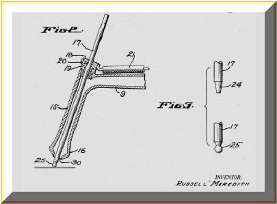
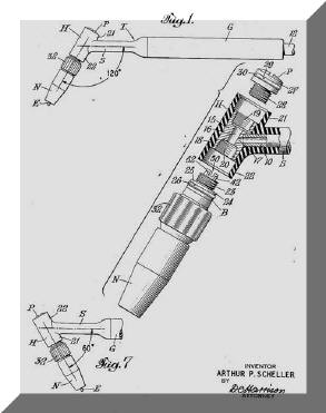
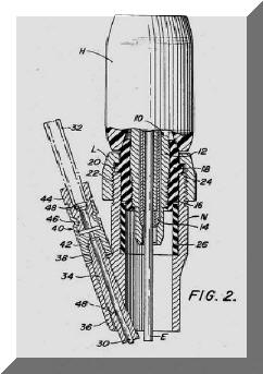
torches. Frank Pilia who worked in the Linde Labs invented and
patented a water cooled TIG torch (# 2,468,806
filed May, 1946; figure left.)
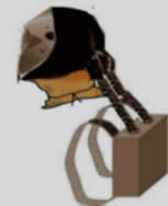
Pete Scheller also worked for Linde and filed a patent in May 1951, # 2,685,631,
for a torch where the head could be bent as needed for access to difficult
to reach areas such as pipe welding (figure lower right.) Meredith
and Northrop Aircraft called the welding process HeliarcR and sold the patent
and trademark rights
to the Linde Division of UCC. Linde, unlike Northrop, had
the
incentive to spend the needed funds and manpower to develop the process
since their business was manufacturing and marketing inert
(and other industrial) gases. They developed a whole series of Heliarc
brand
torches. Frank Pilia who worked in the Linde Labs invented and
patented a water cooled TIG torch (# 2,468,806
filed May, 1946; figure left.)
Pete Scheller also worked for Linde and filed a patent in May 1951, # 2,685,631,
for a torch where the head could be bent as needed for access to difficult
to reach areas such as pipe welding (figure lower right.)
[ Some
two decades after these early inventions, I worked
on various projects at the Linde Labs with
Frank Pilia and Pete Scheller
who were very creative engineers. One, which I developed and
patented,
a High Speed Electroslag
system, Pete Scheller designed the mechanical tractor device.
I also worked with Frank Pilia on another mechanism to propel the unit up the plate. Note, Linde (now renamed Praxair) sold their welding equipment and filler
metal business in the 1980's and the Heliarc Brand
products transferred to the new company L-TEC (a name I chose as VP of marketing for the new company) and when the business was sold it is now owned and marketed by ESAB.] |
 |
 |
|
In
addition to numerous torch patents, Linde developed systems to improve shielding and allow the tungsten electrode to
protrude further from the gas cup for better visibility while still providing the
needed excellent shielding.
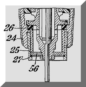
Another colleague, Gene
Gorman, invented the first “gas lens” as it was
referred to in his patent filed April 1960, US 3,053,968. Item # 56
(upper left figure) shown in
patent figure upper left
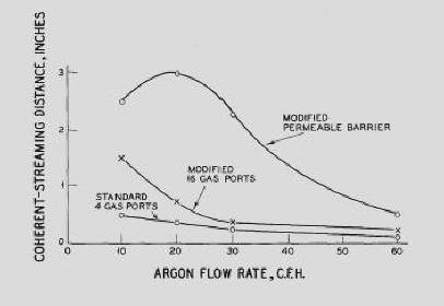
is referred to as a “baffle” with a varying number of holes. As Gorman
notes in the patent teaching, very small holes produced a longer coherent
gas stream substantially without
Turbulence. One material mentioned was a 200 mesh
screen. This produced much better shielding than the porous bronze type
materials he evaluated. When Gorman tested porous bronze materials he
found the gas leaving this type of materials exited in various directions
creating a more Turbulent gas stream!
[Some companies are trying to
sell porous material designs for a gas lens-it is no doubt much easier to
make! Wonder if they ran the Schlieren gas flow tests and made
sufficient welds in various materials to validate its effectiveness, as did
Gorman? See Gas Lens Tests Below. I shared an office with Gene
when I started at the Linde Labs. Gene was developing a three
electrode TIG system for high speed welding of stainless steel in tube
mills. I was developing a three wire
Submerged Arc System that
welded large diameter UOE steel pipe for oil and natural gas transmission,
which welded with 3000 amps!] |
 |
 |
|
 Gorman
shows the resulting gas outflow in one of
the patent figures (above left) and quantifies his finding in a graph.
The graph (above right) shows an improvement in the length of the coherent
gas stream of 6 fold with a device he
called a gas lens. Gorman
shows the resulting gas outflow in one of
the patent figures (above left) and quantifies his finding in a graph.
The graph (above right) shows an improvement in the length of the coherent
gas stream of 6 fold with a device he
called a gas lens.
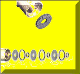
Another
Linde engineer, Cliff Hill, defined an improved method of making a gas lens
in his patent filed in 1961, # 3,180,967. Cliff’s design (patent
figure left) used multiple fine size screens stacked to
provide the Laminar flow needed and as defined in the Gorman patent. He found
these
very fine screens could be
combined with a coarser, more ridged screen on the outside to improve the
durability of the assembly. This construction did not alter the
ability to produce the desired long coherent gas stream. This design
is still used today to produce the best quality shielding gas lens..
Cliff Hill was a very dedicated engineer with many patents in
the TIG torch area. He was a very creative person and a man of few
words. I recall a comment made by Cliff after a lengthy meeting we were
having with engineering. He said, "perhaps we should remove all the
chairs in this conference room and the meetings won't last as long!" |
|
Gas Lens Test
Engineers at ESAB recently
tested several TIG gas lens designs after reviewing
 problems
encountered by a major shipyard. One type was a single piece made of a
porous material and the other had multiple screens similar the genuine
Heliarc design that ESAB markets but with fewer and coarser screens. problems
encountered by a major shipyard. One type was a single piece made of a
porous material and the other had multiple screens similar the genuine
Heliarc design that ESAB markets but with fewer and coarser screens.
The most definitive test results
were observed after carefully making
welds with AC power in aluminum and noting the quality of the cleaning
action. The
amount and consistency of cleaning with the porous, single piece material and
the one with coarse screens was not much better than welds made with a standard
non-gas lens collet. The genuine Heliarc Gas lens with fine internal screens and a
coarser cover screen, as originally patented by Hill (see above,) gave excellent uniform cleaning, much better than the
other two types.
Gorman in his tests in the early
1960's reported in his initial patent (see above) explaining why he found porous materials
did not work - the gas exits in various directions. He discovered
stacked fine screens provided the desired long, laminar gas stream.
Pressed porous materials and the use of fewer,
lower cost, coarse screens are no-doubt much easier to produce and lower in
cost than the properly assembled, more expensive fine screen design. However
the weld results showed this was false economy! |
|
Side Bar
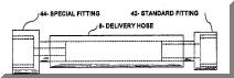
Of
interest, 50 foot long (and sometimes longer) cable
systems are sold for TIG
Torches. The gas hose used for these long cable systems has a small
inside diameter (ID.) It is the same size ID as our much heavier wall
thickness,
custom extruded, hose
utilized for our Gas Saver System (GSS TM.)
Some folks question if our GSS can flow
a sufficient quantity of gas - the
answer is easily! The reason is MIG and TIG gas flows are quite low
compared to the flow rate of oxygen, for example, in oxyacetylene welding and cutting. Also, many companies copy the original Heliarc Torches, Collets, Collet
Bodies and Hose Assemblies and even use the original part numbers. They
also continue to copy the somewhat unusual 12 ½ foot length of the shorter
length
torches. I wonder how many of these copiers know why this unusual
12 ½
foot length was selected? Having worked with the developers of Heliarc
TIG products - I do!
It is a similar intriguing reason as why most TIG and MIG gas delivery
hoses from gas supply to power source (or wire feeder)
are a shielding gas "wasteful" 1/4 inch ID!
Email TechSupport@NetWelding.com
if you'd like to know!
See how our patented "Gas Saver System"
can benefit TIG
welding. |
|
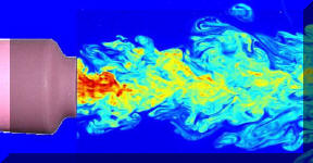
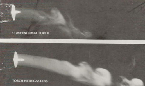 The
gas lens allows the tungsten to be placed well outside the gas cup to
increase visibility (the actual gas flow with and without a gas lens is shown left). The
gas lens allows the tungsten to be placed well outside the gas cup to
increase visibility (the actual gas flow with and without a gas lens is shown left).
TIG Hot Wire
The TIG
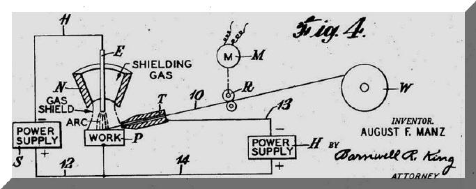
welding process saw a major advancement when an engineer at the Linde Labs invented TIG “Hot Wire.” Gus Manz filed patent, 3,122,629 in February 1962. It
provided TIG quality with MIG deposition rates. It was mostly (and still
is) used for automatic installations. |
|
|
|
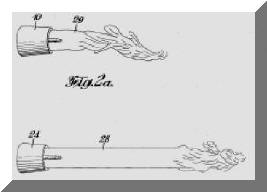
Instead
of slowing adding cold wire to the TIG weld puddle, the “Hot Wire” is heated
just below the melting point and reacts just like squirting toothpaste
into the puddle! The wire exits the contact tip cold (T in the above schematic) and is
heated by a power source (H) as it passes from the tip to the weld puddle with just enough power to make it "mushy" as it
enters! MIG
metal deposition rates are achievable. A subtle but important advantage is
the heated wire burns off all volatile wire surface residuals before it
enters the puddle making it an extremely low hydrogen process. |
|
 Another
colleague, Fritz Saenger, in patent 3,588,464 filed in April 1969, defined a
potentially very useful product, a manual TIG hot wire torch. This
torch design made it easy for a welder to add the “Hot Wire.” It takes
this integrated approach to achieve a system that will work in production
better than
simple add-on approaches. Another
colleague, Fritz Saenger, in patent 3,588,464 filed in April 1969, defined a
potentially very useful product, a manual TIG hot wire torch. This
torch design made it easy for a welder to add the “Hot Wire.” It takes
this integrated approach to achieve a system that will work in production
better than
simple add-on approaches.
Other TIG Innovations:
There
were other innovations such as very high frequency power that constricts the arc
and
multi-electrode systems that increased speeds in production such as
welding on stainless tube mills. Flexible and silicon covered TIG
torches were also introduced. Today’s microprocessor controlled inverter power
systems also make TIG welding easier to use and more controllable.
Note:
Heliarc is a registered trademark of ESAB Welding & Cutting
|
|
See History of
Other Welding Processes:
MIG (GMAW)
Sub Arc
Electroslag
Friction Stir Welding |
|
 New
innovations are still occurring in the welding industry. Our recent
inventions optimize MIG (and TIG) shielding gas flow at the weld start (Patent Number 6,610,957; figure left and Patent Numbers 7,015,412 and 7,019,248) These devices reduce the excess "gas blast" at each weld start. This significantly reduces gas waste
that published
data shows typically exceeds over
60%
of what is used! Reducing shielding gas waste can save a
MIG user typically about half the gas being used while improving weld start quality. Our
Patent 7,462,709, (December 2008, defines a
device
that allows most
flowmeters to be locked at the desired settings avoiding excess wasted gas.
Reducing waste
is very important in a competitive world environment. New
innovations are still occurring in the welding industry. Our recent
inventions optimize MIG (and TIG) shielding gas flow at the weld start (Patent Number 6,610,957; figure left and Patent Numbers 7,015,412 and 7,019,248) These devices reduce the excess "gas blast" at each weld start. This significantly reduces gas waste
that published
data shows typically exceeds over
60%
of what is used! Reducing shielding gas waste can save a
MIG user typically about half the gas being used while improving weld start quality. Our
Patent 7,462,709, (December 2008, defines a
device
that allows most
flowmeters to be locked at the desired settings avoiding excess wasted gas.
Reducing waste
is very important in a competitive world environment.
A major producer of Industrial Gases and Cryogenic Tanks, Air Products, and a leading Airplane Builder have purchased over 300 GSSs for their TIG Welders to improve weld start quality and cut gas use 30 to 40% .
|
|
 In
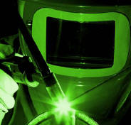
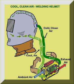
2012/2013 we were issued two patents related to improving a welders environment.
These welding helmet designs not only filter the air entering the helmet
they also cool the air using a Thermoelectric Cooling Module. Research shows cooling
the head helps cool the body. In
2012/2013 we were issued two patents related to improving a welders environment.
These welding helmet designs not only filter the air entering the helmet
they also cool the air using a Thermoelectric Cooling Module. Research shows cooling
the head helps cool the body.
Excessive heat is a common complaint of
welders. This helmet helps solve the excess heat problem by
providing cooled, clean, breathable air. Note patent covers a number of configurations including typical welding PAPR construction and possible use of a backpack arrangement. With the new very low allowed manganese fume levels (4 times lower than Phosgene, the WW I poison Gas!) this patented helmet design is even more important! Welders will like wearing it versus a conventional PAPR or quality respirator since it also helps their hot working environment! CLICK To See Web Page Discussing Fume Details.
We are searching for a company to
license these designs, including large fabricators employing a number of
welders who would benefit from the reduced heat and better environment.
Contact
Jerry_Uttrachi@NetWelding.com if interested.
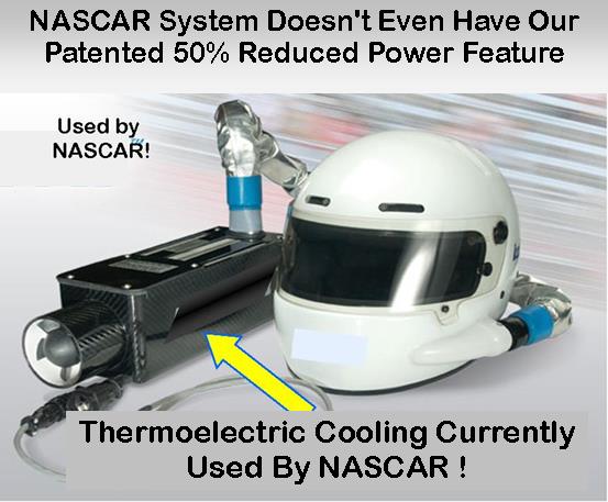
Of interest some NASCAR teams are currently using a thermoelectric device to cool hot drivers! Their light weight compact device does not even use our patented idea that reduces power requirements by 50% or more.
|
|
Have a MIG Welder?
Improve Weld Start Quality and
Have Shielding Gas Cylinder Last at Twice as Long!
Note: Our Patented
GSS
is Not Available in "Stores"
We Focus on Saving NOT
Selling Shielding Gas"
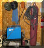
A home shop fabricator
in Georgia with a Miller TM 175 amp welder
purchased a 50 foot Gas Saver System (
GSS
TM
) so he could use a larger cylinder
and mount it on the wall of his shop. He wrote:
"The system works great.
Thanks for the professional service and
a great product."
Click To See His Home Shop
A Professional
Street Rod Builder Had This to Say:
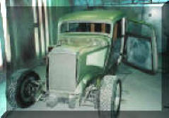
With their standard MIG welder gas delivery hose the peak shielding flow at
weld start was measured at 150 CFH. That caused air
to be sucked into the gas stream causing poor weld starts. With the replacing their existing
hose, the peak flow surge at the weld start was about 50 CFH. Total gas use
was cut in half.
Kyle Bond, President, quickly saw the improvement
achieved in weld start quality as a significant advantage! Kyle, an
excellent automotive painter, was well aware of the effects of gas surge
caused by pressure buildup in the delivery hose when stopped. He has to
deal with the visible effects in the air hose lines on the spray gun in his
paint booth! The paint surge is visible and creates defects unless the gun
is triggered off the part being painted! We can’t do that with our MIG gun!
GAS SAVER SYSTEM (GSS TM)
PURCHASE INFORMATION
GSS
Customer Testimonial: PDF Download |
See YouTube Videos
Including Our Patented MIG Shielding
"Gas
Saver System" (GSS)
Science of MIG
Shielding Gas Flow Control
Why MIG Gas Waste
Detailed Review of GSS
Short Overview of GSS-90 Seconds
What User Say About
GSS
Welding Race Cars
Rat Rods-Then and Now
Welding: Go Green
Lincoln Busiensss Philosophy NEW REVISED 2019 with 2014 Book by Lincoln President Don Hastings
|
|


