|
Selecting Filler Metal
Selecting the proper welding filler metal and techniques
requires an understanding of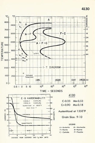 the metallurgy of the base material and the weld metal that develops from an
admixture of the 4130 and the filler metal.
the metallurgy of the base material and the weld metal that develops from an
admixture of the 4130 and the filler metal.
The graph on the left was
taken from a US Steel "Atlas of Isothermal Transformation Diagrams."
These graphs define the metallurgical structure that occurs in various
steels when they are cooled. This one defines that we can expect to
have high hardness, brittle Martensite form when 4130 is cooled at a
particular rate.
The graph at the bottom of the page shows the structure that formed when
a bar of 4130 was heated to 1550 deg F then one end spayed with water.
Note that from about 3/16 inch from the quenched end the microstructure is
almost all Martensite. The hardness in this area is 50 RC. The
equivalent tensile strength for that hardness is about 250,000 psi.
Very strong but also brittle meaning a small crack will easily propagate.
If one made a chisel from that material it would break on the first blow!
If we wanted a chisel we would heat it after quenching to "Temper" the
Martensite to a lower strength and make it far less brittle.
The reason for understanding the 4130 IT diagram, particularly the End
Quench Hardenability Test (Called a Jominy Bar, after the inventor,
Walter E. Jominy) will become apparent as we present additional information
below.
|
|
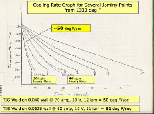 Many years
ago, for a Masters Thesis, I made a Jominy bar from a weld
deposited in a steel that had about 105,000 psi yield and about 120,000 psi
ultimate strength. I also plotted the cooling curves at numerous
points along the Jominy Bar. (No Excel at that time, had to use
graph paper! Note that Walter Jominy only sited cooling rates
at 1100 deg F, not sufficient for my Professor! Had to use a fast
response Light Beam Visicorder, thermal coupes at 1/8 inch intervals along
the bar etc!) Calculations were also made defining the
cooling rate in welds made in 1 inch thick plate with the submerged arc
welding process. The accompanying graph was developed from that data.
The cooling rates for TIG welds made in thin material are also noted on the
graph. Many years
ago, for a Masters Thesis, I made a Jominy bar from a weld
deposited in a steel that had about 105,000 psi yield and about 120,000 psi
ultimate strength. I also plotted the cooling curves at numerous
points along the Jominy Bar. (No Excel at that time, had to use
graph paper! Note that Walter Jominy only sited cooling rates
at 1100 deg F, not sufficient for my Professor! Had to use a fast
response Light Beam Visicorder, thermal coupes at 1/8 inch intervals along
the bar etc!) Calculations were also made defining the
cooling rate in welds made in 1 inch thick plate with the submerged arc
welding process. The accompanying graph was developed from that data.
The cooling rates for TIG welds made in thin material are also noted on the
graph.
|
|
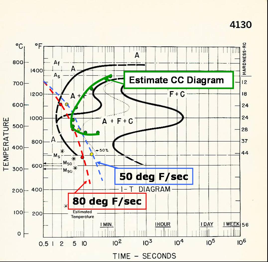
Estimated cooling
rates for several TIG welds in tubing are shown in the accompanying graph in
red and blue lines. The cooling rates are fast since welding volts and amps are relatively
low and the energy efficiency of TIG is low,
about 50%. Calculations for cooling rate are presented on this page:
CLICK.
From the IT
diagram we can estimate a continuous cooling diagram using a technique
suggested by Grange and Kiefer. It is shown with the green line superimposed on the
IT diagram. Also shown is the cooling rate for a TIG weld made on
0.040 inch thick material which is about 50 deg F/sec at about 1100 deg F. For 1/16 inch thick material the TIG cooling rate
would be about 62 deg F/sec, between the two curves. The fast 80
deg/sec cooling rate would occur if small fillets are made on 0.093 inch
thick material. This information is directly related to the weld heat
affected zone (HAZ). These cooling rates can produce some amount of
Martensite in the HAZ. The structure in the weld metal will depend on the weld rod or wire selected as well as
the amount of admixture of 4130. For example, very small fillet welds
may have mostly melted 4130 in the deposit which can create potential
cracking problems.
|
|
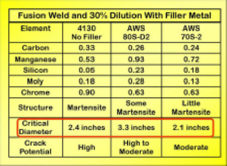 The table
on the left shows the estimated weld metal structure of: 1) a weld made in
4130 without filler metal (called an autogenous deposit), 2) with 30%
ER80S-2 diluted into the 4130 and 3) ER70S-2 rod diluted the same 30% into the 4130. The resulting chemistry
is a simple ratio of the materials assuming TIG welding with Argon shielding gas and
minimum carbon or other
element loss. The table
on the left shows the estimated weld metal structure of: 1) a weld made in
4130 without filler metal (called an autogenous deposit), 2) with 30%
ER80S-2 diluted into the 4130 and 3) ER70S-2 rod diluted the same 30% into the 4130. The resulting chemistry
is a simple ratio of the materials assuming TIG welding with Argon shielding gas and
minimum carbon or other
element loss.
The data showing "Critical Diameter" was developed from a
book on Steel Hardenability by Crafts and Lamont. It defines the
diameter of a bar, that when heated to 1500 deg F and quenched in water
will have 50% Martensite in the center. Notice the deposit with 30%
ER80S-D2 filler rod is much more hardenable than even the 4130.
An austenitized and quenched bar 3.3 inches in diameter of this material would have 50% Martensite
in the center
versus only a 2.4 inch bar for 4130 . The deposit has significantly
higher Manganese and Moly than the 4130 or the deposit made with ER70S-2.
|
|
A deposit made with ER70S-2 in 4139
tubing will most likely have a
slightly lower tensile strength than Normalized 4130. When mixed with
the melted 4130, it will probably be 85,000 to 90,000 psi versus the ~95,000 psi in 4130
depending on how the material was processed. This joint strength can
be increased for intersecting tube joints by making
the fillet size slightly larger.
I have seen
comments on forums about ER70S-2 and ER70S-6 only having a tensile strength
of 70,000 psi. These statement may have been made based on the AWS
designation which indicates a MINIMUM of 70,000 psi is needed
to label the product. That is NOT what is typically found. The following
data is from a TIG weld deposit made with and ER70S-2 rod with essentially
no dilution into the base plate. The information is from published ESAB
data: Tensile Strength was 82,000 psi with a very ductile 31% elongation and
170 ft-lbs Charpy "V" notch impacts at -20 degrees F test temperature. That
is very ductile and tough! When diluted into the high carbon 4130 the strength will
increase.
Conversely, using ER80S-D2 because it contains moly (more than twice that
contained in
4130) may provide a higher strength than needed or desired. For example, an
undiluted weld made with this alloy produced a tensile strength of 110,000
psi and only 22% elongation. ER80S-D2 is often used to weld a Q&T alloy
developed many years ago by US Steel called T-1. It is a structural steel
which has a minimum tensile strength of 110,000 psi, more than normalized
4130 which is typically 95,000 psi. It also has only about 0.15 carbon
making it easier to weld. The 80 in the ER80S-D2 designation does not
define what the actual strength of a deposited weld made with that alloy
will produce-only the minimum to be able to label the product with that
designation.
WELD QUALITY
It is very important to check
weld quality and understand the types of defects that could be encountered when
welding 4130.
Check your weld procedures and keep them consistent. You should make some
sample welds and bend them to destruction to assure failure occurs only after
considerable bending has taken place. Look for porosity or cracks that may
have been present in the weld. It would be a wise investment to hire the
services of an American Welding Society
(AWS)
Certified Welding Inspector (CWI). There are over 20,000 registered.
In fact many of them are members of the 60,000 member AWS. They can
advise on procedures and what to check for such as small undercuts at the weld
toe of fillet welds that can lead to premature failure.
Consistently following the
proper weld procedures and knowing how to check for possible weld problems is of
major importance. Be sure to employ the skills of a qualified
welder who has experience welding this material. Also inspection of the
final welds by an Certified Welding Inspector (Certified by The American Welding
Society) is highly recommended.
|
|
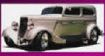
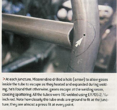 This
is a photo from an interesting article in the March 2007 issue of "Hot Rod
Magazine." The whole ridged elaborate cage was made from 4130 tubing. This
is a photo from an interesting article in the March 2007 issue of "Hot Rod
Magazine." The whole ridged elaborate cage was made from 4130 tubing.
Note they used ER70S-2 welding rod
and made all joints with TIG welding. Have to believe this was a
mocked up photo since the description says the tube ends were ground to
almost a "press fit." This is far from that and unacceptable for
making any type of weld!
Cleaver idea to use the drilled
hole to relieve hot gases in closed tubing joints. |
|
 An
article in the April 2010 issue of the AWS Welding Journal entitled "Best
Practices for GTAW (TIG Welding) 4130 Chrome-Moly Tubing"
defines welding parameters and practices need to make quality welds
in race car tubing joints. It defines practices used by a race car
shop. They also recommend ER70S-2 welding rod for most welding
and when high strength is needed, with a sacrifice in ductility, ER80S-D2.
The article states that excellent fit up is essential. They provide a rule of
thumb for setting welding amperage of using 1 amp per 0.001 inch of wall
thickness. This suggests 35 amps for 0.035 inch and 80 amps for 0.080
inch wall thicknesses. Gas flow of 15 to 20 CFH is suggested.
They mention the use of a "Gas Lens" and a small cup size so the tungsten
electrode can protrude out further for visibility and access to the joint.
Welding in 4 quadrants; two
90 deg segments opposite each other than completing the remaining two
segments is recommended. They suggest using smaller rod diameters, generally no
larger than the wall thickness. The article presents a number of other
suggestions regarding welding conditions from a company with successful
experience. Slow pulsing is suggested either with a foot control or
pulse settings built into the welder. An
article in the April 2010 issue of the AWS Welding Journal entitled "Best
Practices for GTAW (TIG Welding) 4130 Chrome-Moly Tubing"
defines welding parameters and practices need to make quality welds
in race car tubing joints. It defines practices used by a race car
shop. They also recommend ER70S-2 welding rod for most welding
and when high strength is needed, with a sacrifice in ductility, ER80S-D2.
The article states that excellent fit up is essential. They provide a rule of
thumb for setting welding amperage of using 1 amp per 0.001 inch of wall
thickness. This suggests 35 amps for 0.035 inch and 80 amps for 0.080
inch wall thicknesses. Gas flow of 15 to 20 CFH is suggested.
They mention the use of a "Gas Lens" and a small cup size so the tungsten
electrode can protrude out further for visibility and access to the joint.
Welding in 4 quadrants; two
90 deg segments opposite each other than completing the remaining two
segments is recommended. They suggest using smaller rod diameters, generally no
larger than the wall thickness. The article presents a number of other
suggestions regarding welding conditions from a company with successful
experience. Slow pulsing is suggested either with a foot control or
pulse settings built into the welder.
TIG welding (also called Heliarc welding an ESAB trade name) or the official AWS designation, Gas Tungsten Arc
Welding (GTAW) requires more skill than MIG welding. However it allows
separate control of welding heat and metal addition. Currents can be
set at very low levels for thin material allowing the operator to watch the
puddle and assure complete weld penetration. |
|
If a Searc Engine Found This Page 1st- - - We'd Suggest
a Visit to The Basic Welding 4130 Page; Then Return. Click
Here
This page presents the technical information that supports
the reasons for the suggestions found on the "Basic, Welding 4130" page.
Like Math?
Want to
see the calculations for weld cooling rates and references?
CLICK
HERE.
Check Out Welding
Math Site |
|
|
Book:
"Advanced Automotive Welding"
Author: Jerry Uttrachi
(President of WA Technology)
This 176 page book includes detailed metallurgical
information about welding Chrome-Moly
CLICK for Book Details |
|
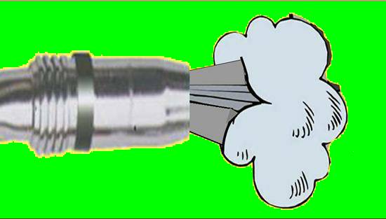 The
"Gas Blast" at MIG Weld Starts Causes Problems: The
"Gas Blast" at MIG Weld Starts Causes Problems:
1)
Shielding Gas Waste
- typically 50% of gas used
2) Inferior Weld Quality
- due to air pulled in gas stream
See Patented
Gas Saver System (GSS)
Solution
GSS
Works for TIG Welders with Foot Pedal or Thumb Control
|
|
This Page Presents Technical Details of Welding 4130
for Other Information:
Click for BASIC 4130 WELDING
DETAILS
Click for
EQUATIONS
defining weld cooling rate in tubing
Click for
WELDING HEAT TREATED 4130 CHROME MOLY
Click for
METALLURGICAL DEFINITIONS
Click for WELDING A BETTER
STEEL; HY 130 |
 Stop
Wasting Shielding Gas!! Stop
Wasting Shielding Gas!!
See YouTube Videos
Including Our Patented MIG Shielding
"Gas
Saver System" (GSS)
Why MIG Gas Waste
Detailed Review of GSS
Short Overview of GSS-90 Seconds
What User Say About
GSS
Welding Race Cars
Rat Rods-Then and Now
Welding: Go Green
Engineering A
Pro Street / Street Rod
|
|
MIG Gas Delivery and the Small Block Chevy
Evolved in a Similar Way and Time!
Both had Advances and
Setbacks Before
They Were Optimized!
Click
for a PDF Report on the Similarities |
|
Thanks to those "Car Crazy" folks who have purchased
the Gas Saver System and commented on the improved starts and reduced gas usage
they have achieved. Many purchased our 6 foot prefitted
GSS,
Part Number WAT FB6,
a 3 and 4 foot system, FB3 & FB4, are also available.
ONE PAGE SUMMARY
PURCHASE
GSS PRODUCT
FREE Corvette Accessory Installation Info
|
"WARNING: "Weld
Safely"
|


