|
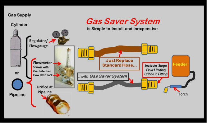
How The Gas Saver System (GSS)
Works
Below: Standard Gas Delivery Hose and a GSS Shown
in a Welding System
|
 |
The Following Flow
Control Sequence Defines Key Reason for Gas Waste:
 |
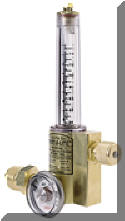 With cylinder
gas supply a Regulator/Flowmeter (pic left) pressures range from 25 to 80 psi depending
on gas type and model. Most
Regulator/Flowgauges (pic right) typically With cylinder
gas supply a Regulator/Flowmeter (pic left) pressures range from 25 to 80 psi depending
on gas type and model. Most
Regulator/Flowgauges (pic right) typically  require 40
to 60 psi setting for 35 CFH flow rate require 40
to 60 psi setting for 35 CFH flow rate
With pipeline gas supply, flow rate is usually set with a Flowmeter or sometimes a fixed orifice. Most pipelines are set at 50 psi so when welding stops the 3 to 7 psi in the gas delivery hose when welding, very quickly raises to 50 psi, all ready to create the "Gas Blast" when welding starts!.
|
|
When welding, the needle valve or fixed
sized orifice reduces the gas delivery hose pressure to 3 to 7 psi needed to
establish the desired flow rate.
The exact pressure depends on the torch type/length, spatter build-up in
the torch gas diffuser and nozzle, bends in torch cable, etc. It
will vary while welding. In fact the pressure will vary
automatically, See "Automatic Flow
Compensation." |
|
When
welding stops, gas continues to flow though the needle valve or orifice
and will quickly reach the pipeline or regulator pressure of 25 to 80.psi.
This extra pressure increases the volume of gas stored it in the
hose. How much extra gas is stored? Depending on the pressure
it can be 7 times the
physical hose
volume. Click to See
Calculations. |
|
That excess stored gas "Blasts Out" of
the MIG gun nozzle in a
few seconds when welding starts. With normal gas delivery
hoses, we have measured peak surge flows of 250.CFH. The high surge flow rate not only
wastes gas, it pulls air into the shielding gas stream causing excess
spatter and possibly internal porosity in the weld start! |
| |
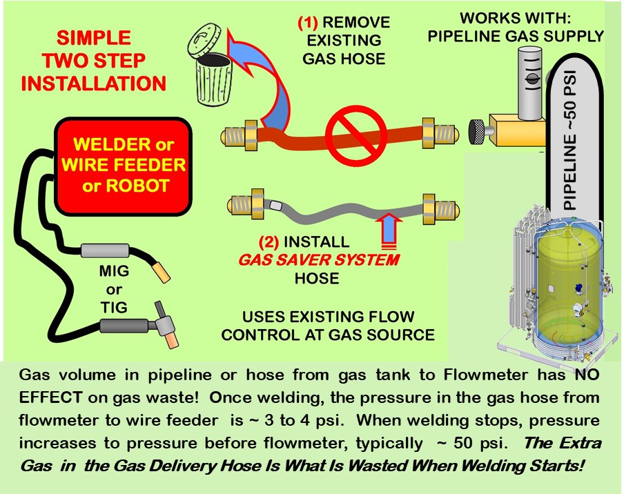
A Fabricator asked if the size and pipeline volume going to their flow controls has an effect on gas waste. The answer is NO! The reason is the needle valve (or in some cases a very small orifice) used to control the flow rate drops the pressure WHILE WELDING in the gas hose from the flow control to the welder or wire feeder to as low as 3 to 4 psi. That is all the pressure needed to flow the typical 30 to 35 CFH MIG gas flow. [Don't confuse that with CFM (cubic feet per minute) that is often quoted for air compressors etc. 30 CFH = only 0.5 CFM! Much lower than any air compressor. It's about human breathing rate while resting!] Exceeding ~50 CFH causes turbulence and air is pulled into the shielding gas stream casung excess spatter!
However every time WELDING STOPS, the gas continues to flow through the needle valve and quickly fills the hose with the typical pipeline pressure of about 50 psi. That is ~10 times the pressure when welding. That excess gas presure also stores a lot of EXCESS GAS that blasts out as soon as the MIG Gun trigger is pulled for the next weld. Short welds and Tack welds- waste a lot of gas! |

See "Why Gas Waste"
Video
See
Demo and Solve Gas Waste |
|
HOW THE
GSS
REDUCES THIS EXCESS GAS AND WASTE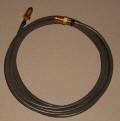
The patented
GSS uses a smaller inside diameter
hose to reduce the volume of stored gas when welding stops. In addition,
a surge flow orifice built into the feeder end hose fitting limits the
peak surge flow at the weld start so it does not pull air into the shielding
gas stream. This orifice and the smaller ID hose create a small
pressure drop that also reduces the excess gas volume and waste.
BOTTOM LINE
When welding
stops, the GSS stores 80 to 85%
less gas than a conventional gas delivery hose.
Therefore there is 80 to 85% less gas to waste at the weld start. The
built-in flow rate limiter avoids having a turbulent starting gas shield-it's
that simple.
To avoid a high peak flow rate that just pulls air into the shielding gas stream the patented GSS also has a peak flow limiting orifice built into the gas fitting on the welder end. The GSS has no moving parts and no knobs to adjust. Any reasonable, non-turbulent steady state gas flow rate can be set. (Note if welders are setting very high gas flow rates (we have measured flow at the gun nozzle of 150 CFH with the flow control knob opened wide) the GSS will limit these excess flow rate settings.) There is still
a controlled amount of extra gas at the weld start to quickly purge the weld
start area. System pressure remains above 25 psi to retain
Automatic Flow Compensation.
(If controlling
maximum allowable gas flow rates to meet Welding Procedure Specifications (WPS) is desired - click to see our patented Flow Rate Limiter and
Lock.) |
| |

Have
Questions? Wonder how this simple patented product can save so much
shielding gas? The following
are some specific Questions:
Click Link to View Answers
-
What is the Ideal Gas Delivery System?
-
Is
their documentation of a Fabricator Saving Over 60% Shielding Gas?
-
Why is Enough
Extra Gas Needed at MIG Weld
Starts?
-
How does Automatic Flow Compensation
Work and Why a Minimum of 25 psi Regulator Pressure is Needed to Achieve
it?
-
What is
the Payback of the Gas Saver System? Note: It
is Usually Measured in Weeks However When Adding New Welding Machines, it
Could Be Immediate!- -See Payback Calculations
and "Just Do It !"
-
Why
is My Existing Gas Delivery Hose a Wasteful 1/4 " ID?
-
Why do Simple
Orifices Not Work to reduce gas waste? Why they give a false
savings impression!
-
What About Using
Orifices To Control Flow at a Pipeline Gas Supply?
-
See
what a Praxair Representative said in a Published Technical Article
about the Average Fabricator Using 5 to 6 Times the
Shielding Gas They Should!
Have another question? Email
 |

Free Technical Paper, "MIG
SHIELDING GAS
CONTROL"
CLICK ICON for PDF DOWNLOAD |

Purchase Gas Saving Products |
Purchase Training
Aids |
|
Purchase
Flow Rate Limiter |
Purchase Wire Feeding
Aids |
| |
Purchase Orifice Flow Control
System |


