


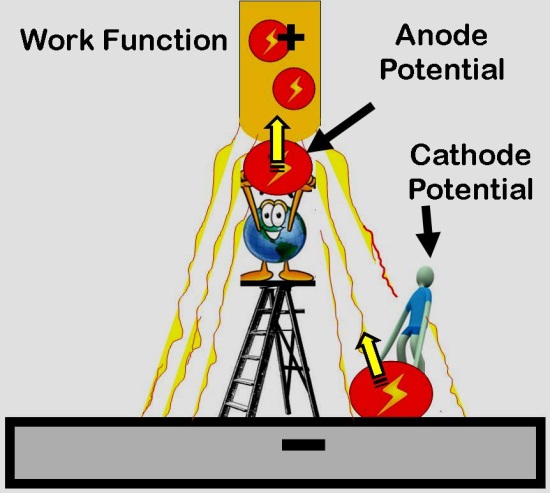
CLICK for Partner's Mobile Friendly Website Setting MIG Gas Flow |
|||
CUT GAS USE in "HALF" - By Eliminating Starting Gas Waste Prices Start at $80 . CLICK FOR DETAILS: |
|||
Download PDF of Tech Paper : History of MIG Shielding Gas Flow Control and Devices Download PDF of Tech Paper : Competitive Capitalism Created Most Modern Welding Processes |
|||
|
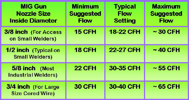
MIG Shielding Gas Flow Rate Chart |
|||
|
For Metric (SI) units
- Multiply CFH x 0.47 =
liters/min |
|||
TESIMONIAL: Beau Straley Improved Weld Quality and Saved >60% Shielding With the GSS installed I even increased the gas flow rate and appearance and quality of my welds improved dramatically. That's a winning combination in my book! Thank you for a wonderful product that does what you say!" Using Beau's numbers that is 50%/75% = 67% Less Gas Used with the GSS! |
|||
|
|||
Over 10,000 Patented Gas Saver Systems (GSS's) used at fabricators such as Air Products, Boeing, Caterpillar Tractor etc. See Partial User List. |
|||
|
|||
Why Does Chart Industries have >3000 Gas Saver Systems (GSS's) ? |
|||
Over 15,000 Patented, Inexpensive Gas Saver Systems (GSS's) used by fabricators such as Boeing, Caterpillar, Chart Industries etc.. Many small shops and home hobbyists use a GSS to cut gas use in half. |
|||
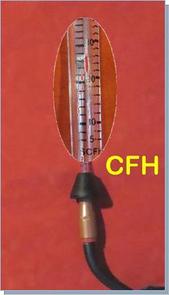
Check the gas flow
exiting the MIG gun nozzle with our portable flowmeter (Part # WAT-PFM) |
|||
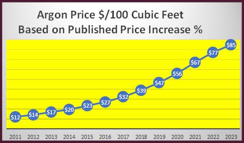
STOP Wasting Gas; Prices will increase as supply will remain short. Can't just import gas for several reasons BUT it's also in short supply elsewhere. We have supplied hundreds of our patented Gas Saver Systems (GSS) to China, India and Saudi Arabia as well as many US fabricators. |
|||
 TESTIMONIAL: Received a repeat order from a fellow in Hawaii. I asked about the cost of a cylinder refill there! He responded: TESTIMONIAL: Received a repeat order from a fellow in Hawaii. I asked about the cost of a cylinder refill there! He responded: “I’m just a weekend welder with a home shop. I have four 125 cubic foot tanks, two Argon and two 75 Argon/25 CO2. They cost $260 and $275 per tank to fill! With the Gas Saver System ( GSS ) my weld starts look better and my gas saving is 40%." |
|||
|
|||
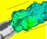 The "Gas Blast" at Weld Starts Causes a Turbulent Gas Stream That Sucks in Air Producing Excess Spatter and Reduces Weld Quality. The "Gas Blast" at Weld Starts Causes a Turbulent Gas Stream That Sucks in Air Producing Excess Spatter and Reduces Weld Quality. That turbulent gas surge pulls in air for a short time even after flow rate reduces. For short welds, that can the whole weld! Our patented Gas Saver System (GSS ) cuts gas use in half by reducing the wasteful "Gas Blast"at weld starts while improving weld start quality. Prices Start at $80, Less Than a Cylinder Refill! |
|||
Over 10,000 Patented Gas Saver Systems (GSS's) used at fabricators such as Air Products, Boeing, Caterpillar Tractor etc. See Partial User List. |
|||
To maintain our focus on "Saving not Selling" shielding gas our patented products are sold direct on this website and are "Not Available in Stores." |
|||
|
MIG shielding gas flow is set and measured
as cubic feet of gas per hour (CFH) NOT pressure in psi.
Unlike oxyfuel welding and cutting, MIG gas flow rates are very low.
The gas pressure in the hose going into a wire |
|||
|
MINIMUM FLOW RATES:
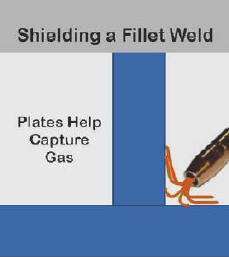
In a low draft environment when making a fillet weld the lowest suggested flows are usable. The plates being welded help retain the shielding gas. Shielding is more effective with the help of the gas retention at these low rates. The vertical member is also effective in providing a natural block for drafts. |
|||
|
TYPICAL FLOW RATE RANGE: For butt welds there is no vertical plate to help retain the shielding gas. In addition there is nothing to help maintain the gas shield when drafts are encountered. Therefore the gas flow rate needs to increase to assure quality gas shielding and proper weld coverage. The range shown in the table is typical of that used in industry (or that should be used!) As wire size, welding current and the gun nozzle to work distance are increased gas flow rates should increase. |
|||
|
MAXIMUM SUGGESTED FLOW RATE:
In the presence of drafts, higher flow rates can be used - up to a limit. It is important to avoid creating Turbulent flow that will pull air into the shielding gas stream. In 1893 Osborne Reynolds defined the flow rates that establish smooth Laminar flow (needed for quality MIG shielding) versus Turbulent flow that causes moisture laden air to mix with the shielding gas stream. Using that information and extensive tests The Welding Institute in the UK defined the maximum flow rates to maintain Laminar flow. In a recent published article the manager of welding R&D for Praxair states; "flow rates in excess of 50 CFH cause atmospheric gases to be pulled into the gas stream causing poor weld quality." Click and see references numbers 3 & 4 on this web page. |
|||
|
Reinforcing the maximum flow rate values is unpublished research that defined flow rates needed to handle drafts. In a 4 to 5 mph controlled draft using Argon based shielding gas and a standard 5/8 inch diameter MIG gun nozzle, 45 CFH flow rate had less internal weld porosity as measured by X-ray than 65 CFH flow rate. This reinforces the need to keep flow rates below about 55 CFH with a 5/8 inch nozzle. |
|||
|
WIND SHIELD:
During a "Best Practices" tour in Japan of bridge fabricators we saw gas shielded MIG being used at a construction site to butt weld large girder vertical seams. Simple flexible wind shields were used that were moved as welding progressed. If drafts are an issue, a larger 3/4 inch ID nozzle and increased shielding gas flow can be used up to the suggested maximum of 65 CFH BUT NO HIGHER. |
|||

Unfortunately some folks believe;
"If Some is Good,
More Must Be Better" when it comes to setting shielding gas
flow! We have often seen flowmeters with the ball pinned to the top of
the flow gauge tube. Measurements of commercial flowmeters show with
the needle valve opened wide flow rates can be 150 CFH- far
too much for good shielding. Also a fabricator recently called and
said his welding gas distributor told him the 100 CFH flow rate they were
using was fine! It's NOT! We have two patented products that can help solve the problem. The first is our Gas Saver System GSS . It reduces the gas surge at the weld stat saving about half the gas being used. The GSS also limits the maximum flow to a level that avoids excess turbulence. The GSS will limit flow to about half the level that can be set on a flowmeter when the knob is opened wide. Click for Details |
|||
|
The graph on the left is from a production operation where the gas flow rate at each weld start exceeded 75 CFH for 4 seconds. Osborne Reynolds defined that Turbulent flow takes some time to return to Laminar flow even after the flow rate is reduced. Therefore it is probable Turbulent flow existed for 6 or 7 seconds. Note when the company installed our patented Gas Saver System peak flow was reduced to under 90 CFH and it was over 75 CFH for only about a second after the torch switch was pulled. The GSS quickly provided enough extra gas to purge the weld start area but at a flow rate that did not create excess Turbulence. The welder at this repair weld station immediately saw the benefit of the GSS as his welds are all ultrasonically tested. He was having significant problems with weld start porosity and knew the high starting gas surge was a major cause. After 6 months using our patented GSS he said his porosity problems had been eliminated. Note, it only takes about 2 1/2 % air being mixed into the shielding gas stream to exceed the 2% Nitrogen some sources indicate will cause weld porosity. |
|||
Why MIG Gas Flow is in CFH NOT PSI?MIG gas flow is set and measured in cubic feet per hour NOT psi. Unlike Oxyacetylene welding where pressures are set to control flow though a torch - in MIG welding much lower gas flow rates are used. At these low flow rates, during welding, restriction changes occur due to spatter build-up in the gun nozzle and gas diffuser, the small gas passage in the gun cable is bent and looped, etc. These restrictions could cause large flow changes. When MIG was developed, the engineers designing the gas flow systems used a principle called "choked flow" that provides Automatic Flow Compensation and maintains the preset flow regardless of the changing flow restrictions. "Choked Flow" works by the fact that gas velocity can not exceed the speed of sound. That is why you see lightening before you hear the thunder! If the low pressures needed to set the required flow were used, when the restrictions changed so would the flow; it could cut preset flow in half! A minimum of 25 psi above a needle valve or flow control orifice is required to obtain "choked flow." Unfortunately this is a much higher pressure than the 3 to 7 psi needed to flow the typical 25 to 30 CFH. This high pressure causes excess gas volume to be stored in the gas delivery hose (from cylinder or pipeline to welder) each time welding stops. This excess stored gas " blasts" out of the MIG nozzle at each weld start. This gas surge not only wastes a lot of gas but causes excess turbulence pulling air into the gas stream, creating inferior weld starts. Our simple, patented GSS solves both the gas waste and "gas blast" problems! NOTE: Don't confuse CFH (cubic feet per hour) with the flow rate of an air compressor measure flow rate in CFM (cubic feet of gas per minute.) For MIG welding, 30 CFH X hr/60 min = 1/2 CFM - pretty low flow rate! Even Experts Get It WRONG!
A quick calculation shows he was probably only getting about 2 psi in the gas hose and in the header pipe when he adjusted the needle valve to get the equivalent of a 0.02 inch hole! Unfortunately TV personalities welding often set a bad safety example as well, welding with short sleeves and occasionally with no gloves! SEE WELD SAFELY |
|||
|
Received an Excellent Question About How an Orifice or Needle Valve Can Set and Automatically Adjust to the Proper Pressure Drop to Maintain Consistent MIG Gas Flow?
The Answer is Detailed so a PDF was
Produced:
|
|||
|
|
Purchase Flow Rate Limiter |
|
 |
|
|
|
|
|
|
||


 Gas with an FB4 GSS. Beau said, "I received the

 Why Does MIG Wire Melt

 We receive questions asking:
"What MIG shielding gas flow
rate should be used?" Sometimes asking: "What pressure should be set?"
This is understandable since even the
American Welding Societies 5 volume, 4000 + page "Welding Handbook" has
everything you would want to know about MIG welding (GMAW) but very little shielding
gas flow rate recommendations! There are statements saying excess shielding
gas flow creates turbulence and pulls in oxygen and nitrogen creating
problems but no mention of what the maximum flow rate should be! We
have done the research and defined the maximum levels.
We receive questions asking:
"What MIG shielding gas flow
rate should be used?" Sometimes asking: "What pressure should be set?"
This is understandable since even the
American Welding Societies 5 volume, 4000 + page "Welding Handbook" has
everything you would want to know about MIG welding (GMAW) but very little shielding
gas flow rate recommendations! There are statements saying excess shielding
gas flow creates turbulence and pulls in oxygen and nitrogen creating
problems but no mention of what the maximum flow rate should be! We
have done the research and defined the maximum levels.
 feeder/welder, while welding, typically
varies from 3 to 8 psi. Flow restrictions in the
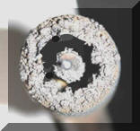
small size MIG gun and cable gas passages vary when welding. This pressure changes as spatter builds in the
gun nozzle and gas diffuser. A significant pressure drop change occurs in the small gas passage in the gun cable as it is
bent while welding. Since the gun cable gas passage often doubles as the hose holding the spiral wire
liner-it partially clogs with copper flakes and debris. Pressure must increase to offset these added restrictions. A method of
feeder/welder, while welding, typically
varies from 3 to 8 psi. Flow restrictions in the
small size MIG gun and cable gas passages vary when welding. This pressure changes as spatter builds in the
gun nozzle and gas diffuser. A significant pressure drop change occurs in the small gas passage in the gun cable as it is
bent while welding. Since the gun cable gas passage often doubles as the hose holding the spiral wire
liner-it partially clogs with copper flakes and debris. Pressure must increase to offset these added restrictions. A method of
 A
number of factors determine the minimum shielding gas flow rate needed. The MIG gun
nozzle size is an important factor. Small ID nozzle sizes require less
flow to get quality shielding. Drafts are also very important as is
the type of weld joint.
A
number of factors determine the minimum shielding gas flow rate needed. The MIG gun
nozzle size is an important factor. Small ID nozzle sizes require less
flow to get quality shielding. Drafts are also very important as is
the type of weld joint.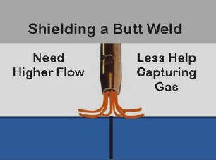

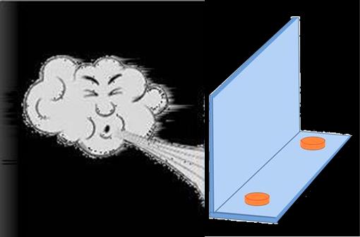 When MIG welding, if drafts exceed about 4 to 5 mph, a wind shield or block must be used. In some cases that can
be as simple as positioning your body between the source of the draft and
the weld.
A simple wind shield can
be made from sheet metal and held to the work with small magnets. Many welding codes limit gas shielding processes to welding with drafts lower than 5 mph.
When MIG welding, if drafts exceed about 4 to 5 mph, a wind shield or block must be used. In some cases that can
be as simple as positioning your body between the source of the draft and
the weld.
A simple wind shield can
be made from sheet metal and held to the work with small magnets. Many welding codes limit gas shielding processes to welding with drafts lower than 5 mph. 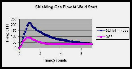 Another
problem with excess flow is the "Blast of Gas" that occurs at the weld start
with conventional gas control systems. We have measured peak flows at
the weld start in
excess of 250 CFH.
Another
problem with excess flow is the "Blast of Gas" that occurs at the weld start
with conventional gas control systems. We have measured peak flows at
the weld start in
excess of 250 CFH.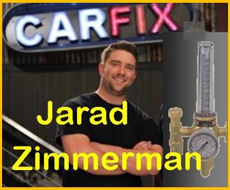 One of my favorite TV car shows is CAR FIX. Jarad and Lou treat each other with respect and provide excellent "How To" welding discussions. Even their technical explanations are "usually excellent." However in a January 2016 episode where Jarad was purging the inside of a stainless pipe making headers, and set a purging flowmeter at what he said was 15 psi! The flow ball went to 15 but that was 15 CFH NOT Pressure. I'd give him the benefit of a slip, but it's TV and they have lots of bloopers that get cut. He missed that one and I know from his discussions of engine gas flow etc, he knows the difference!